Method and equipment for controlling multicast service in WLAN (Wireless Local Area Network)

A multicast service and multicast group technology, applied in the field of communication, to achieve fast switching and eliminate frequent interruptions

Active Publication Date: 2010-12-22
ALCATEL LUCENT SHANGHAI BELL CO LTD
View PDF3 Cites 11 Cited by
  • Summary
  • Abstract
  • Description
  • Claims
  • Application Information

AI Technical Summary

Problems solved by technology

[0006] In order to realize the switching of multicast services in WLAN, while concealing different types of WiFi APs from user terminals, and concealing the complexity of WLAN multicast service proces

Method used


Image

  • Method and equipment for controlling multicast service in WLAN (Wireless Local Area Network)
  • Method and equipment for controlling multicast service in WLAN (Wireless Local Area Network)
  • Method and equipment for controlling multicast service in WLAN (Wireless Local Area Network)

Examples


no. 1 example

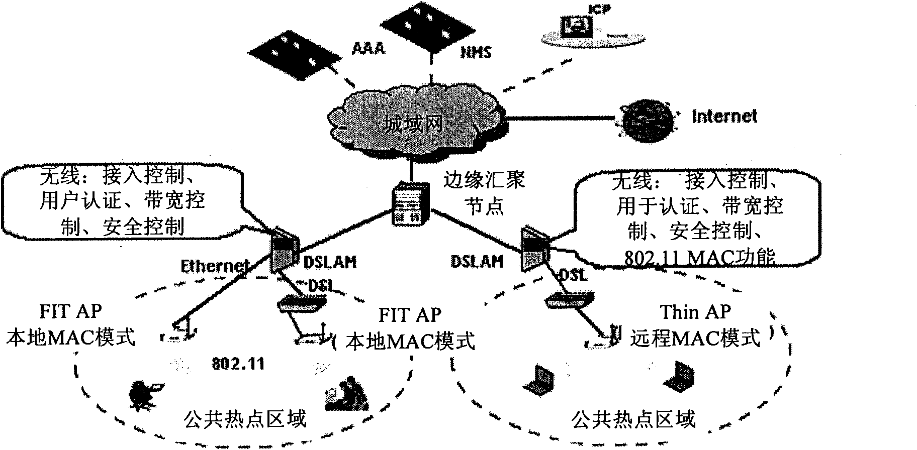
[0034] Refer to the attached Figure 2-6 A first embodiment of the present invention is described. In the first embodiment of the present invention, the WLAN multicast agent handles multicast control, multicast service forwarding, and fast multicast service for user terminals (in this embodiment, WiFi terminals) located in the coverage area of ​​the Thin AP switch.

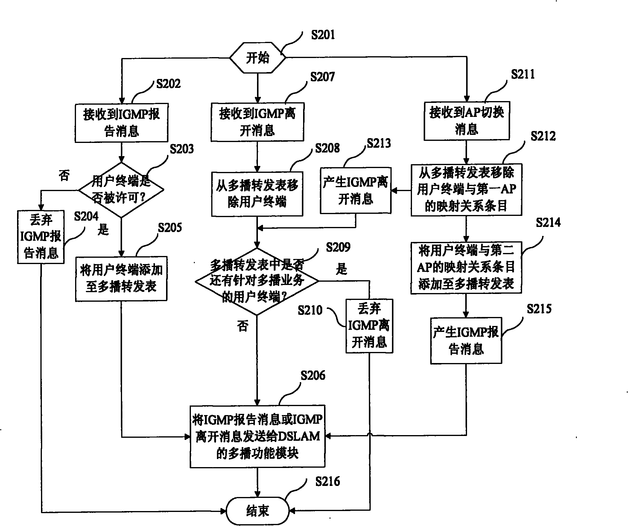
[0035] figure 2 A flowchart showing a method for controlling a multicast service of a WiFi terminal located in a Thin AP coverage area in a WLAN through a WLAN multicast proxy according to the first embodiment of the present invention. Such as figure 2 As shown, the method starts in step S201. In step S202, the WLAN multicast agent receives a multicast service registration message (for example, an IGMP report message) from the user terminal about the user terminal requesting to join the multicast group. In this case, the flow goes to step S203 to check the user terminal's access right to the multicast group...

no. 2 example

[0073] Refer to the attached Figure 7-11 A second embodiment of the present invention is described. In the second embodiment of the present invention, the WLAN multicast agent handles multicast control, multicast service forwarding, and fast multicast for user terminals (in this embodiment, WiFi terminals) located in the coverage area of ​​the Fit AP Business switching.

[0074] Figure 7 A flowchart showing a method for controlling a multicast service of a WiFi terminal located in a Fit AP coverage area in a WLAN through a WLAN multicast agent according to a second embodiment of the present invention. Such as Figure 7 As shown, the method starts at step S701. In step S702, the WLAN multicast proxy receives a multicast service registration message (for example, an IGMP report message) from the user terminal about the user terminal requesting to join the multicast group. In this case, the process goes to step S703 to check the user terminal's access right to the multicas...


PUM


Abstract

The invention discloses a method for controlling a multicast service in a WLAN (Wireless Local Area Network) by a wireless local area network (WLAN) multicast proxy, comprising the following steps of: when the WLAN multicast proxy receives a first multicast service register message from a user terminal, responding to the first multicast service register message for configuring a multicast forwarding table of the WLAN multicast proxy; and when the WLAN multicast proxy receives an AP (Assembly Point) switching message generated by an AC (Access Controller) in a DSLAM (Digital Subscriber Line Access Multiplexer), responding to the AP switching message for configuring a multicast forwarding table of the WLAN multicast proxy. In the invention, the WLAN multicast proxy can conceal the complexity of a WLAN network infrastructure to the user terminal and the traditional multicast transmitting module in fixed access equipment for transmitting the multicast service. In addition, the WLAN multicast proxy is conductive to realize the quick service switching when a WiFi (Wireless Fidelity) terminal moves from one AP in the same WLAN ESS (Wireless Local Area Network Executive Support System) to the other AP.

Description

technical field [0001] The present invention relates to the communication field, and more specifically relates to a method for controlling multicast services in WLAN. The present invention can hide the complexity of the WLAN network infrastructure from the user terminal and the multicast function module in the existing fixed access equipment used for multicast service transmission, and can also realize the multicast service in the WLAN. Fast switching between different APs. Background technique [0002] In recent years, a wireless local area network (Wireless Local Area Network, WLAN) has been widely deployed around the world. There are several deployment architectures for WLAN networks. In order to better manage large-scale WLANs, a centralized WLAN architecture is gradually adopted. [0003] For Digital Subscriber Line (Digital Subscriber Line, DSL) network operators who want to deploy a large-scale WLAN network and realize nationwide roaming, such as China Telecom, the...

Claims


Application Information

Patent Timeline
IPC IPC(8): H04W4/06H04W4/08H04W60/00H04W84/12H04W88/18
Inventor 马松伟郑军张青山
Owner ALCATEL LUCENT SHANGHAI BELL CO LTD
Why Eureka
Try Eureka