
Antenna for discharging surge current

A surge current, antenna technology, applied in the direction of the antenna, antenna parts, antenna support/installation device, etc., to achieve the effect of maintaining characteristics

Inactive Publication Date: 2010-12-22
ACE TECH
View PDF3 Cites 0 Cited by
  • Summary
  • Abstract
  • Description
  • Claims
  • Application Information

AI Technical Summary

Problems solved by technology

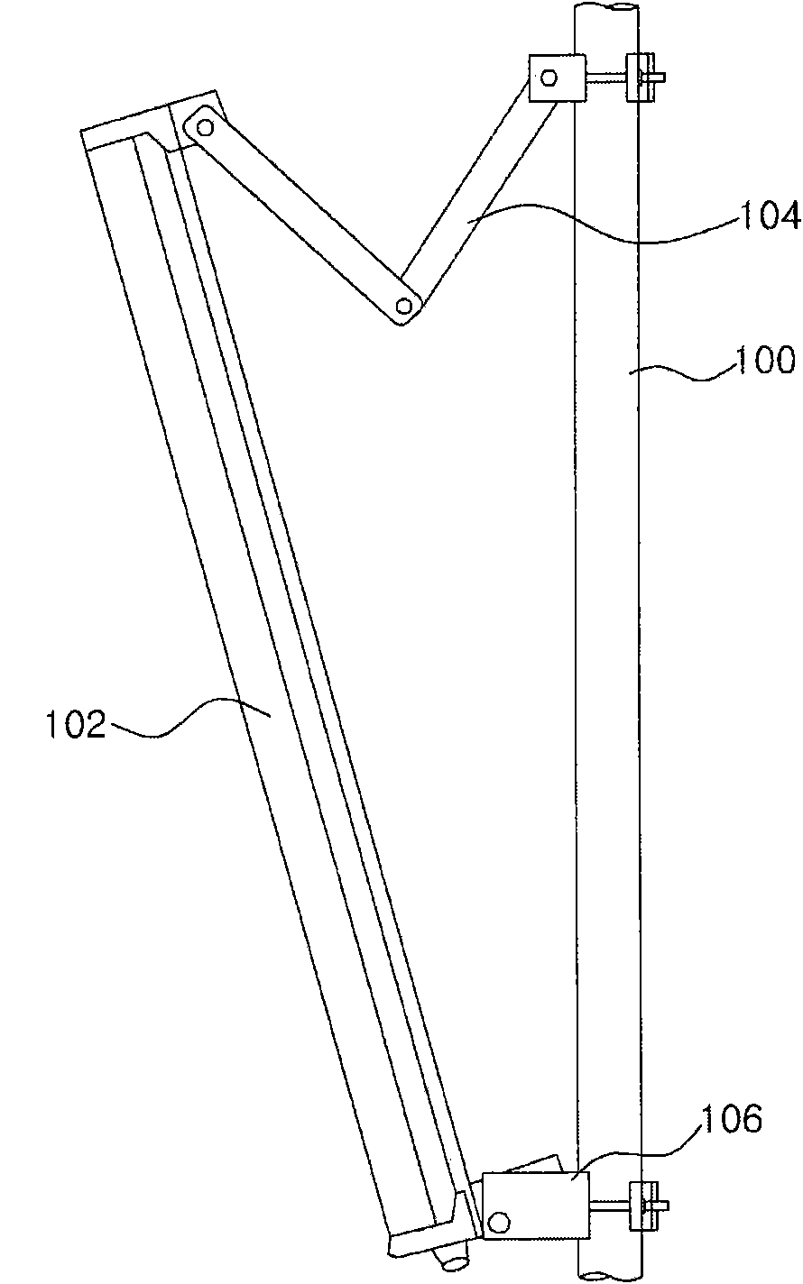
In such a case, since no additional discharge path is formed in the antenna 102, the surge current affects elements in the antenna 102

Method used


Image

  • Antenna for discharging surge current
  • Antenna for discharging surge current
  • Antenna for discharging surge current

Examples


Embodiment Construction

[0034] Example embodiments of the invention are disclosed herein. However, specific structural and functional details disclosed herein are merely representative for purposes of describing example embodiments of the invention which, however, may be embodied in many alternative forms and should not be construed are limited to the example embodiments of the invention set forth herein.

[0035] Therefore, while the invention is capable of various modifications and alternative forms, specific embodiments of the invention have been shown by way of example in the drawings and will be described herein in detail. It should be understood, however, that there is no intention to limit the invention to the particular forms disclosed, but on the contrary, the intention is to cover all modifications, equivalents, and alternatives falling within the spirit and scope of the invention. In the description of the figures, the same reference numerals refer to the same elements throughout.

[003...


PUM


Abstract

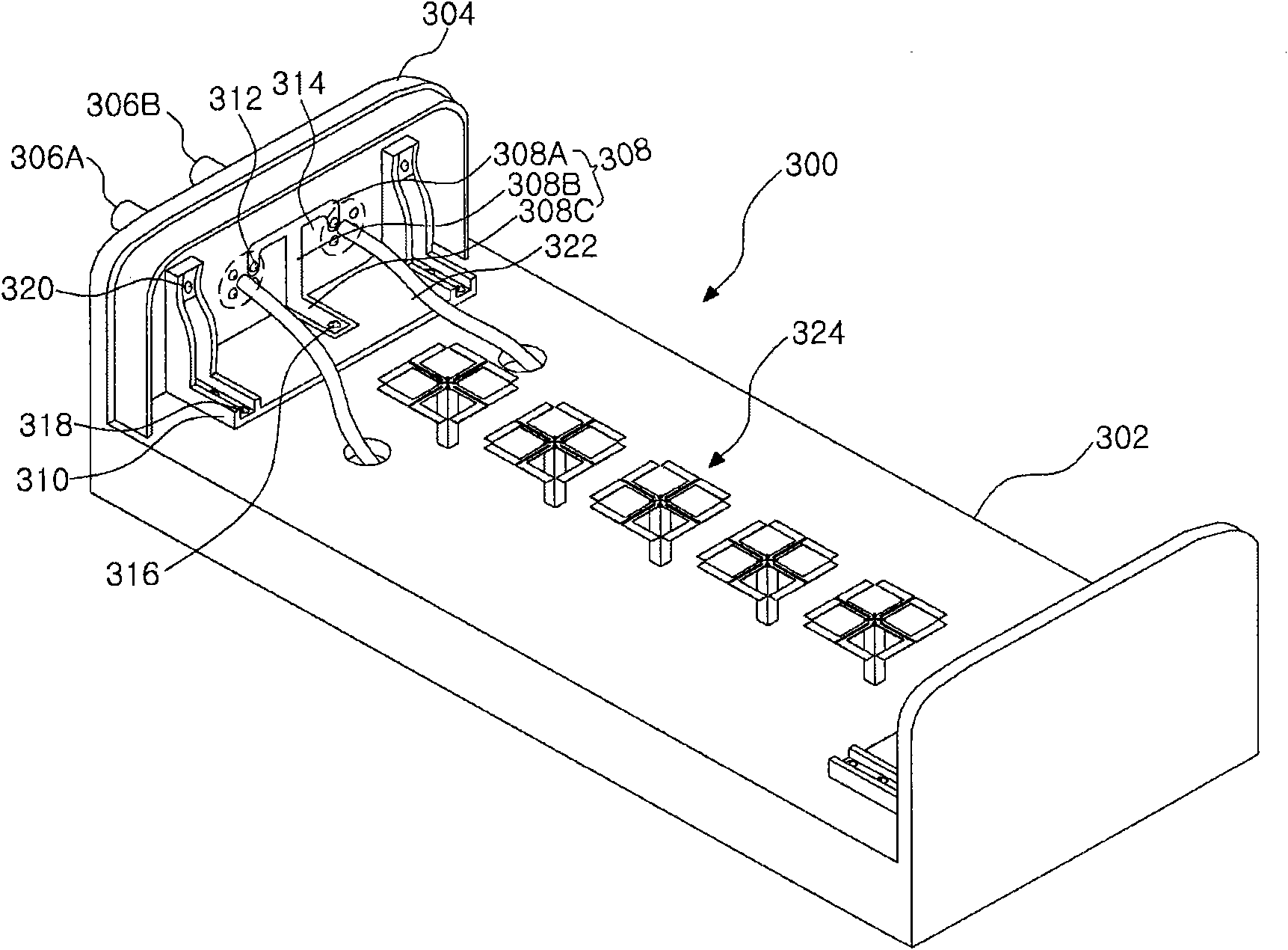
An antenna for discharging surge current to an outside through a ground member and a clamp member coupled to the ground member is disclosed. The antenna includes a first conductive member, a clamp member as a conductor, and a first ground member configured to connect electrically the first conductive member to the clamp member, and be a conductor. Here, surge current is discharged through a current path formed through the first conductive member, the first ground member and the clamp member.

Description

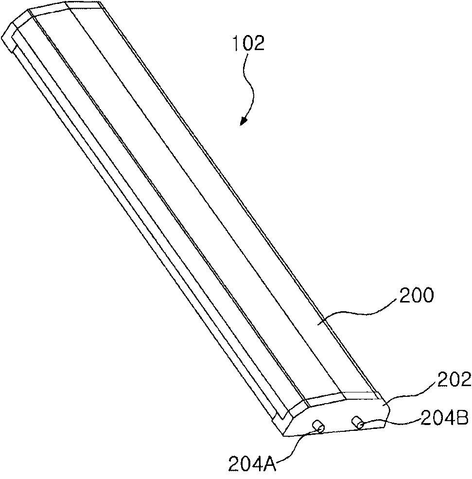
technical field [0001] Exemplary embodiments of the present invention relate to an antenna for discharging surge current, and more particularly, to an antenna for discharging surge current to the outside through a ground member and a clamp member coupled to the ground member. Background technique [0002] The antenna transmits / receives electromagnetic waves by radiating a beam in a specific direction. In particular, the directional antenna set up in the base station is directly exposed to the external environment, and has features such as figure 1 structure shown in . [0003] figure 1 is a view showing the structure of a general antenna set up in a base station. figure 2 is showing figure 1 A perspective view of the antenna in . [0004] exist figure 1 In this example, the antenna 102 is combined with the antenna support member 100 by the clamps 104 and 106 . Here, since the antenna 102 is set up in the base station, the antenna 102 is exposed to the external enviro...

Claims


Application Information

Patent Timeline
Patent Type & Authority Applications(China)
IPC IPC(8): H01Q1/50
CPCH01Q1/50H01Q1/002H01Q1/246H01Q1/26H01Q15/14
Inventor 郑民锡吴秉一
Owner ACE TECH
Learn More