Mounting method and alignment rod for connecting pin of main piston of actuator and slide block of sensor

A technology of connecting pins and main pistons, which is applied in metal processing, metal processing equipment, manufacturing tools, etc., can solve the problems of time-consuming and labor-intensive technical requirements, affecting the accuracy of sensors, and low assembly efficiency, so as to ensure the accuracy of use and shorten the assembly time , The effect of high assembly efficiency

Inactive Publication Date: 2010-12-29
FLIGHT AUTOMATIC CONTROL RES INST
View PDF3 Cites 2 Cited by
  • Summary
  • Abstract
  • Description
  • Claims
  • Application Information

AI Technical Summary

Problems solved by technology

This assembly method has three disadvantages: first, it uses a lot of labor and requires the cooperation of two people to complete it; second, the assembly efficiency is low, alignment is very difficult, time-consuming and labor-intensive, and requires high skill
The existing assembly method needs at least 30 minutes to complete the assembly; third, in the alignment process, it is necessary to repeatedly apply external force to the spring in the sensor slider, which is very unfavorable to the performance and structure of the sensor, and may affect the accuracy of the sensor

Method used


Image

  • Mounting method and alignment rod for connecting pin of main piston of actuator and slide block of sensor
  • Mounting method and alignment rod for connecting pin of main piston of actuator and slide block of sensor
  • Mounting method and alignment rod for connecting pin of main piston of actuator and slide block of sensor

Examples


Embodiment 1

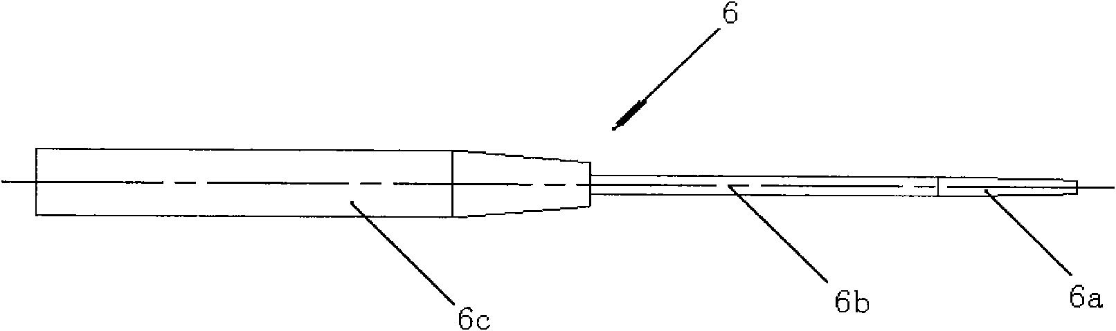
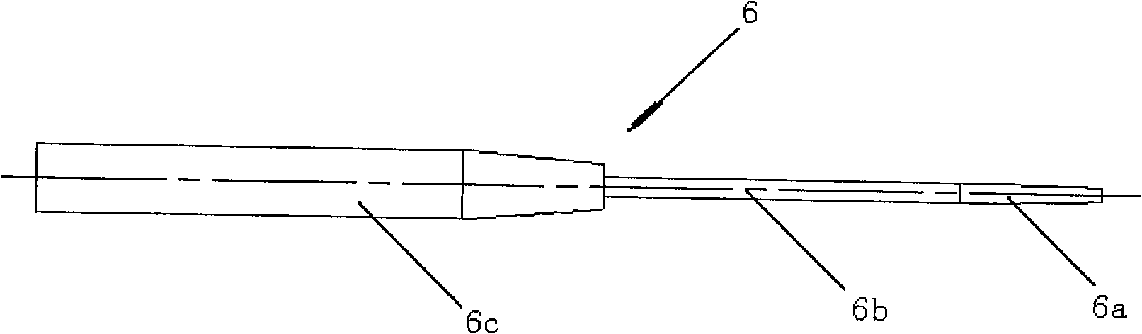
[0018] Embodiment 1, the taper α of the conical section 6a of the leveling rod is 15°, and the diameter of the end of the conical section 6a is 1.8mm. The installation steps are as follows:

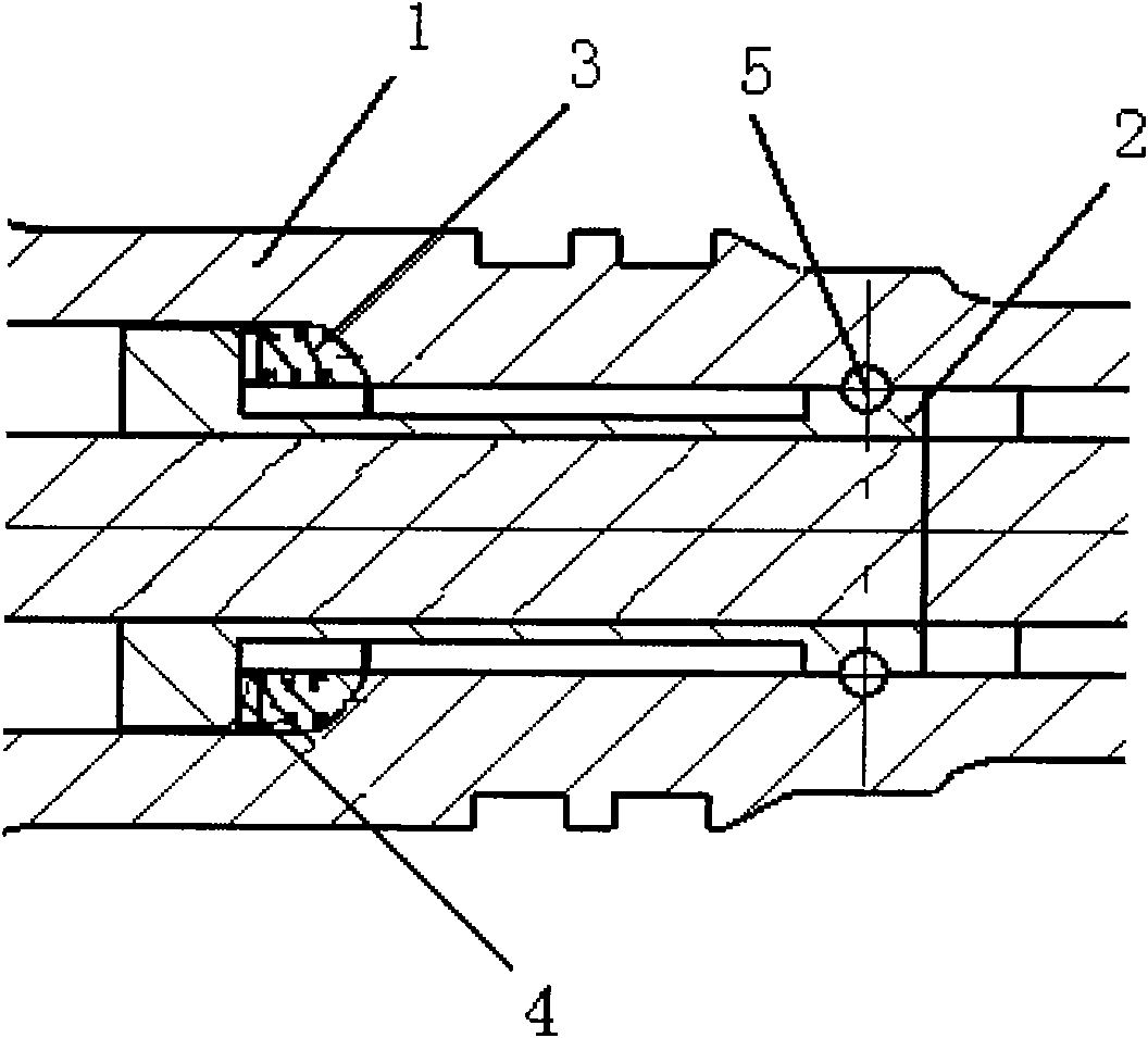
[0019] 1. Match the adjusting gasket 4; by matching the adjusting gasket 4 with different thicknesses, the edge of the part where the section of the ring mounting groove on the sensor slider coincides with the mounting hole of the connecting pin on the main piston is along the center of the mounting hole of the connecting pin. The minimum distance in the line direction is 2.2mm;

[0020] 2. Align the center of the cross-section of the annular mounting groove on the sensor slider and the mounting hole of the connecting pin on the main piston;

[0021] 3. Install the connecting pin to complete the installation of the main piston and the connecting pin of the sensor slider.

Embodiment 2

[0022] In Embodiment 2, the taper α of the conical section 6a of the straightening rod is 17°, and the diameter of the end of the conical section 6a is 2mm. The installation steps are as follows:

[0023] 1. Match the adjusting gasket 4; by matching the adjusting gasket 4 with different thicknesses, the edge of the part where the section of the ring mounting groove on the sensor slider coincides with the mounting hole of the connecting pin on the main piston is along the center of the mounting hole of the connecting pin. The minimum distance in the line direction is 2.5mm;

[0024] 2. Align the center of the cross-section of the annular mounting groove on the sensor slider and the mounting hole of the connecting pin on the main piston;

[0025] 3. Install the connecting pin to complete the installation of the main piston and the connecting pin of the sensor slider.


PUM


Abstract

The invention belongs to assembly technology of actuators, and relates to an improved mounting method and a special alignment rod for a connecting pin of a main piston of an actuator and a slide block of a sensor. The mounting method comprises the following steps of: selecting and matching an adjusting gasket 4; aligning the section of an annular mounting groove on the slide block of the sensor with the centre of a connecting pin mounting hole on a main piston; and mounting the connecting pin. The alignment rod of the invention consists of a conical section [6a], a cylindrical section [6b] and a handle [6c]. The mounting method and the alignment rod have the advantages of low used labor, high assembly efficiency and capability of ensuring the accuracy of the sensor.

Description

technical field [0001] The invention belongs to the actuator assembly technology, and relates to the improvement of the installation method of the main piston of the actuator and the connecting pin of the sensor slide block and a special alignment rod. Background technique [0002] For the structure after installation of the main piston of the actuator and the connecting pin of the sensor slider, refer to figure 1 , the sensor wire package is connected with the cylinder body of the actuator, the movable iron core of the sensor is connected with the sensor slider 2, and the sensor slider 2 is connected with the main piston 1 through two connecting pins 5 . On the sensor slider 2 there is an annular mounting groove with a semicircular section, and on the main piston 1 there are two connecting pin mounting holes. The connecting pin 5 is located in the connecting pin installation hole of the main piston 1 and the annular installation groove of the sensor slider 2 to realize the...

Claims


Application Information

Patent Timeline
Patent Type & Authority Applications(China)
IPC IPC(8): B23P19/10
Inventor 朱朝锋
Owner FLIGHT AUTOMATIC CONTROL RES INST
Why Eureka
Try Eureka