High-temperature gate valve of combined wedge plate

A high-temperature gate valve and gate technology, applied in the field of combined gate high-temperature gate valves, can solve the problems of increasing valve switching torque, reducing valve service life, friction and wear, etc., and achieving the effect of reducing valve switching torque and prolonging service life.

Inactive Publication Date: 2010-12-29
FOUNDER VALVE GRP SHANGHAI CO LTD
View PDF5 Cites 12 Cited by
  • Summary
  • Abstract
  • Description
  • Claims
  • Application Information

AI Technical Summary

Problems solved by technology

Although the valve with this structure solves the problem of mutual abrasion between the valve seat and the sealing surface of the valve plate, because the shape of the inner mating surface of the two valve plates is """ shape, due to the existence of double slopes, it will increase the friction of the valve. At the same time, due to the difficulty of processing the double """-shaped combined valve plate, especially the large-diameter valve plate
At the same time, due to the """-shaped combined gate of the split valve, the main block of the gate continues to move under the drive of the drive thread of the valve stem, and there is relative motion with the sealing surface of the valve seat, which will cause friction and wear, especially in the When there are some hard particles in the working medium, the wear will be intensified. Therefore, one side of this valve has a poor sealing effect. Therefore, the seal of this type of valve is directional, and the flow direction is generally marked on the valve.
[0005] In this type of split gate valve, the gate plate has no diversion hole, and when the medium passes through the valve body, eddy current and turbulent flow will be generated, which will seriously scour the valve body and valve seat, reducing the service life of the valve

Method used


Image

  • High-temperature gate valve of combined wedge plate
  • High-temperature gate valve of combined wedge plate
  • High-temperature gate valve of combined wedge plate

Examples


Embodiment Construction

[0018] A preferred embodiment will be given below, and the present invention will be described more clearly and completely in conjunction with the accompanying drawings.

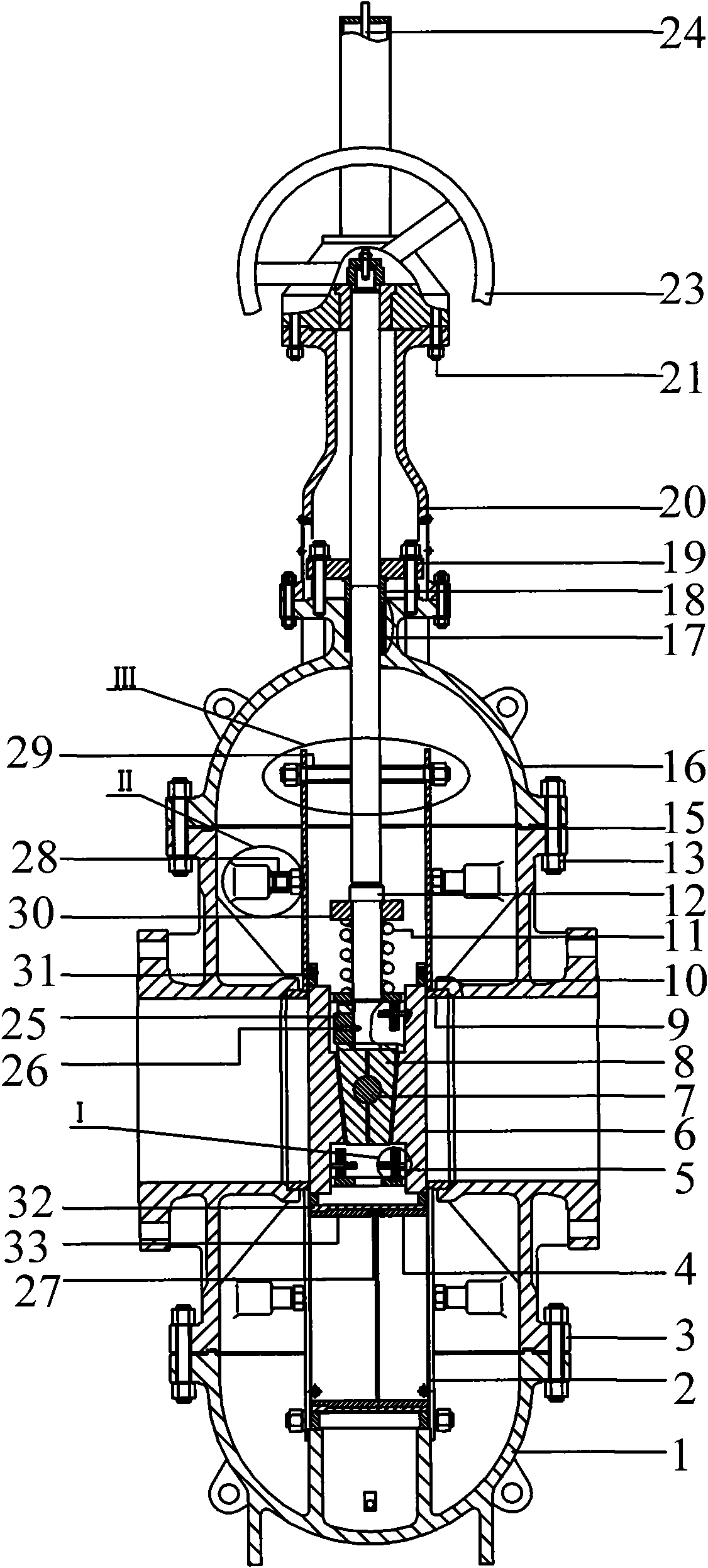
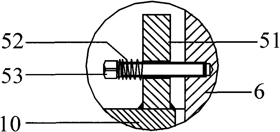
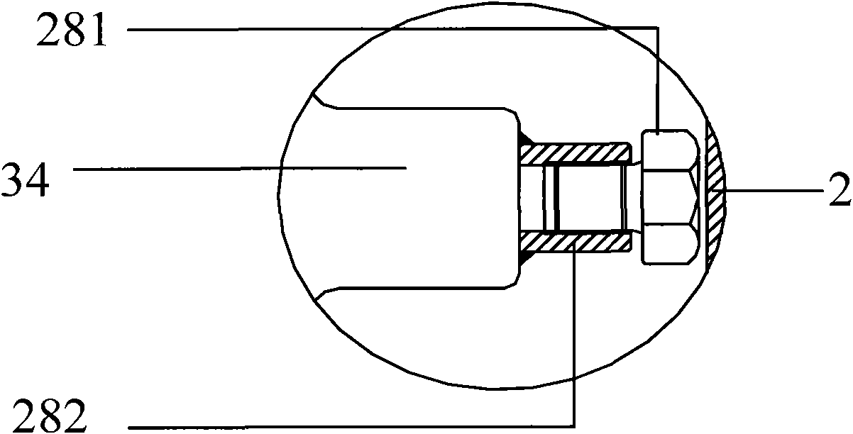
[0019] Such as figure 1 As shown, the combined gate high temperature gate valve of the present invention includes a lower cover 1, a guide plate 2, a valve body 3, a first guide tube 4, an elastic fixing mechanism 5, an outer gate 6, a steel ball 7, an inner gate 8, a valve Seat 9, gate frame 10, first spring 11, valve stem 12, first bolt 13, sealing gasket 15, upper cover 16, sealing packing 17, packing gland 18, packing pressure plate 19, bracket 20, the first Two bolts 21, valve driving device 23, indicator rod 24, joint 25, set screw 26, cylindrical spring 27, outer righting mechanism 28, inner righting mechanism 29, spring pressing plate 30, roller mechanism 31, fixed cylinder 32 and the second Two guide tubes 33. The lower cover 1 is fixed to the valve body 3 by bolts, the upper cover 16 is fixed to ...


PUM


Abstract

The invention discloses a high-temperature gate valve of a combined wedge plate, which comprises external wedge plates, a valve seat, internal wedge plates, a steel ball, an associator, an elastic fixing mechanism, a wedge plate frame and a valve rod, wherein the fitting surface of the external wedge plate and the valve seat is a plane, and the fitting surface of the internal wedge plate and the external wedge plate is an inclined plane; the upper part of the internal wedge plate is provided with a transverse through-hole, and two internal wedge plates are positioned by the steel ball; the associator passes through the transverse through-hole of the two internal wedge plates so as to connect the two internal wedge plates together, and a vertical axial threaded hole connected with the valve rod is arranged on the associator; a pair of wedge plates is composed of the external wedge plates and the internal wedge plates, and is fixed on the wedge plate frame with aid of the elastic fixing mechanism. The high-temperature gate valve of a combined wedge plate of the invention has the advantages of reducing the torque of a valve switch, and prolonging the service life of the valve.

Description

technical field [0001] The invention relates to a high-temperature gate valve, in particular to a combined gate high-temperature gate valve, which can be widely used in high-temperature and high-pressure fields such as the exploitation of heavy oil and geothermal resources, petrochemical industry, medicine, papermaking, and food. Background technique [0002] At present, the commonly used valve plate structure forms of high temperature and high pressure valves mainly include wedge type and split type. Since the valve is suitable for complex working conditions such as high temperature, high pressure, and hard particles, the structural design is ever-changing. However, the ever-changing Not far from the principle, because the thermal expansion of the material is mainly considered for valve sealing under high temperature conditions. In order to ensure the sealing of the valve, the sealing surfaces of the valve plate and the valve seat must be closely bonded, so the linear expans...

Claims


Application Information

Patent Timeline
Patent Type & Authority Applications(China)
IPC IPC(8): F16K3/12F16K3/18F16K27/04F16K3/314F16K3/316
Inventor 方存正王英才李杰林杰
Owner FOUNDER VALVE GRP SHANGHAI CO LTD
Why Eureka
Try Eureka