pds ball valve

A ball valve and valve seat technology, applied in the field of PDS high-frequency ball valves, can solve the problems of reducing the service life of the valve seat spring, shortening the service life of the spring, and increasing the pre-tightening force, so as to reduce the pressure bearing area, prolong the service life, and reduce friction. small effect

Active Publication Date: 2020-12-04
CHONGQING CHUANYI CONTROL VALVE
View PDF5 Cites 0 Cited by
  • Summary
  • Abstract
  • Description
  • Claims
  • Application Information

AI Technical Summary

Problems solved by technology

The traditional PDS high-frequency ball valve seat spring chamber has a dust-proof structure design. The spring chamber is designed in the middle of the spring, and the front and rear ends are blocked by sealing rings. This structure has the phenomenon of increasing the switching torque of the valve and reducing the life of the seat spring. When the medium pressure pushes the spring seat, the spring seat will compress the spring, and the spring compression will increase, making its pre-tightening force increase, and the service life of the spring compression overload will be shortened
At the same time, the pressure-bearing area of ​​the spring seat of this structure is large, the thrust force transmitted by the medium to the valve seat is also greater, and finally the force transmitted to the valve seat by the sum of the spring preload force and the thrust of the medium is also greater, resulting in a large switching torque of the valve and friction. High force, short service life of the valve
The problem still exists in the design and manufacture of the existing PDS high-frequency ball valve is that under the condition of online use of the valve, the tiny solid particles in the medium are easy to enter the spring chamber and accumulate in a large amount in the spring chamber, continuously reducing and eliminating the deformation of the spring, resulting in The spring fails, which affects the switch of the valve and the sealing performance of the valve

Method used


Image

  • pds ball valve
  • pds ball valve

Examples


Embodiment Construction

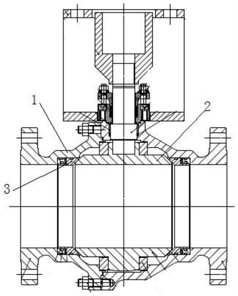
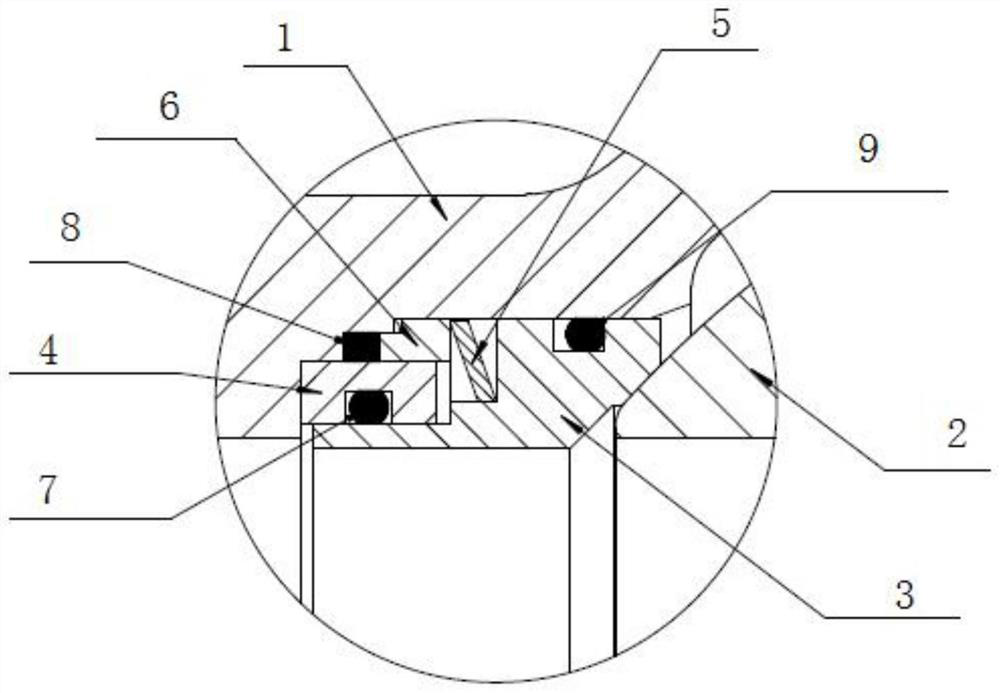
[0018] figure 1 It is the structural representation of the PDS ball valve of the present invention, figure 2 Schematic diagram of the guide components. The PDS ball valve of the present invention includes a valve body 1, a ball core 2, and a valve seat 3. The valve seat 3 is elastically pressed against the spherical surface of the ball core 2, and the rear end of the valve seat 3 is elastically pressed by an elastic member 5. On the spherical surface of the ball core 2, the elastic component can be a disc spring or other elastic components arranged along the direction of the medium fluid. On the side away from the ball core 2, a guide part 4 is provided at the rear end of the valve seat 3 to apply a pre-tightening force to the valve seat 3 to compress the spherical surface of the ball core 2. The guide part 4 provides an initial pre-tightening force and Transfer medium pressure. During use, the thrust of the medium is transmitted to the valve seat through the guide part 4 ...


PUM


Abstract

The invention discloses a PDS ball valve comprising a valve body, a ball core and a valve seat. The valve seat is elastically and tightly pressed to the spherical face of the ball core. A guide component is arranged at the back end of the valve seat and located on the side far away from the ball core, wherein the guide component exerts pretightening force on the valve seat to tightly press the valve seat to the spherical face of the ball core. The guide component provides initial pretightening force for the valve seat and transmits medium pressure to the valve seat. The PDS ball valve can be used for preventing solid particles in the medium from entering a spring cavity, and the medium pressure does not compress the spring in the use process; and meanwhile, the pressure bearing area at thetail end of the valve seat is reduced, so that the push force for the valve seat to be tightly pressed to the spherical surface of the ball core is reduced, the friction force between the valve seatand the spherical surface of the ball core is reduced, the seal performance of the valve is guaranteed, the opening and closing torque of the valve is reduced, and the service life of the valve is prolonged.

Description

technical field [0001] The invention relates to the field of valves for controlling fluid, in particular to a PDS high-frequency ball valve. Background technique [0002] PDS high-frequency ball valves are widely used in polypropylene and other devices, and the total consumption of polypropylene in my country ranks first in the world, but most of the key PDS high-frequency ball valves on domestic polypropylene devices are imported from abroad, especially The polypropylene unloading system (PDS) is the core component of the polypropylene production process. The ball valve configured in it requires fast action and a service life of 1 million times. The traditional PDS high-frequency ball valve seat spring chamber has a dust-proof structure design. The spring chamber is designed in the middle of the spring, and the front and rear ends are blocked by sealing rings. This structure has the phenomenon of increasing the switching torque of the valve and reducing the life of the seat ...

Claims


Application Information

Patent Timeline
Patent Type & Authority Patents(China)
IPC IPC(8): F16K5/20F16K5/06
CPCF16K5/06F16K5/201
Inventor 李松岭李宏伟段大军刘兰吴明祥
Owner CHONGQING CHUANYI CONTROL VALVE
Why Eureka
Try Eureka