Method, terminal and network system for reporting buffer status report

A buffer state, buffer technology, applied in the direction of network traffic/resource management, separation device of transmission path, electrical components, etc.

Active Publication Date: 2010-12-29
ZTE CORP
View PDF4 Cites 106 Cited by
  • Summary
  • Abstract
  • Description
  • Claims
  • Application Information

AI Technical Summary

Problems solved by technology

[0031] The technical problem to be solved by the present invention is to provide a method, a terminal and a network system for reporting the buffer status report, in a wireless network supporting carrier aggregation, to so

Method used


Image

  • Method, terminal and network system for reporting buffer status report
  • Method, terminal and network system for reporting buffer status report
  • Method, terminal and network system for reporting buffer status report

Examples


Embodiment 1

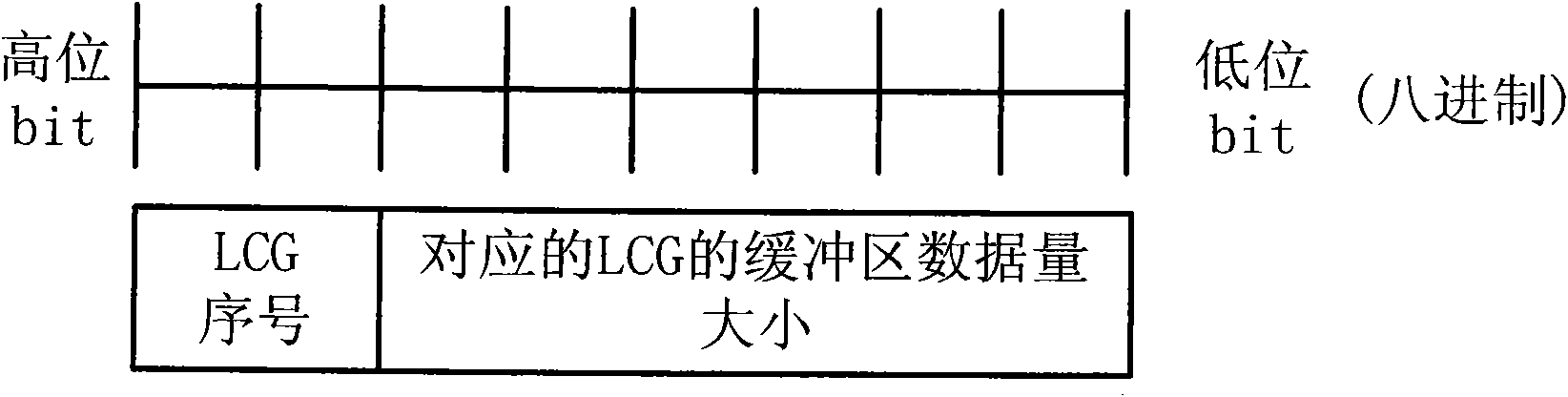
[0151] The composition method of the BSR data unit containing only one LCG buffer status information is as follows: it contains the sequence number information of the LCG, the length of which is log2N bits, and N is the total number of LCGs; the BSR also contains the LCG corresponding to the above sequence number The level information of the amount of data to be transmitted in the buffer zone. The length of the level information of the amount of data to be transmitted in the buffer zone of each LCG depends on how to classify the scope of the amount of data to be transmitted in the buffer zone of the LCG. The current LTE Release 8 standard sets the buffer zone to be transmitted The range of transmitted data volume is divided into 64 levels (that is, the length of the data volume level information is 6 bits), and the maximum accurate actual buffer data volume that can be represented is 150,000 bytes. This embodiment assumes that the maximum accurate actual buffer data that is requ...

Embodiment 2

[0153] The corresponding method between the level of data volume to be transmitted in the buffer and the volume of data to be transmitted in the actual buffer zone is: each level corresponds to a range of data volume, the range of data volume corresponding to adjacent levels is continuous, and the data volume corresponding to each level The size of the range is a fixed value, or an incremental value that increases as the level increases, or a combination of the above two methods. The corresponding relationship between the level of data volume to be transmitted in the buffer zone of the BSR and the actual data volume to be transmitted in the buffer zone of the present invention may be based on the corresponding relationship defined in the prior art (LTE release 8), adding a new corresponding relationship, or The corresponding relationship defined in the prior art may be changed, or a completely new corresponding relationship may be set.

[0154] Taking the class length as 7 bit...

Embodiment 3

[0161] In addition, the corresponding table of LCG buffer data volume level and data volume range defined in LTE release 8 can still be used, but the definition of the corresponding relationship of the table can be changed so that the table can accurately represent the actual LCG buffer data of up to 750,000 bytes quantity. An example is as follows: This example retains the correspondence table between the LCG buffer level and the data volume range defined by LTE release 8, such as Figure 11 As shown, the composition method of the BSR data unit in this example adopts Figure 8 The method shown (the LCG buffer data volume level length is represented by 9bit), Figure 11 The corresponding relationship table shown has only 64 levels, and the maximum can only accurately represent 150000bytes, so this example adds a new definition relationship as follows:

[0162]

[0163] Among them, M is the maximum number of series 63 in the corresponding relationship table, F is the amoun...


PUM


Abstract

The invention discloses a method for reporting a buffer status report. The method comprises the following steps of: triggering the buffer status report and acquiring radio resource information of an uplink component carrier of a radio network by a terminal; constructing one or more buffer status report (BSR) data units according to information on the quantity of to-be-transmitted data at a buffer; and selecting one or more uplink component carriers from the uplink component carriers with available radio resources, and transmitting the buffer status report (BSR) data units to a network side on the radio resources of the selected uplink component carriers. The invention also discloses a network system and the terminal using the method. By applying the method, one or more BSRs are flexibly generated, and proper component carrier resources are selected to transmit the BSR, so that the aims of ensuring transmission accuracy of the buffer status report and saving the uplink radio resource are fulfilled.

Description

technical field [0001] The invention relates to the technical field of wireless communication, in particular to a method, a terminal and a network system for realizing buffer state report reporting in a wireless network. Background technique [0002] In the Evolved Universal Terrestrial Radio Access Network (E-UTRAN for short) of the third-generation mobile communication Long Term Evolution (LTE for short) system, the uplink data is transmitted through the physical uplink Link shared channel (Physical Uplink Shared Channel, PUSCH for short) transmission. An evolved base station (Evolved NodeB, eNB for short) allocates uplink radio resources to each user terminal (User Equipment, UE for short). The access technology used in the E-UTRAN system is OFDM (Orthogonal Frequency Division Multiplexing) technology. Compared with the second-generation mobile communication system, the radio resource management of the E-UTRAN system has a large The characteristics of the process, its w...

Claims


Application Information

Patent Timeline
IPC IPC(8): H04W28/14H04W60/04H04W72/12H04W88/02H04W88/08
CPCH04W72/1284H04W72/1221H04W72/21H04L5/001H04W28/0278
Inventor 戴谦张银成王涛王冠宙
Owner ZTE CORP
Why Eureka
Try Eureka