Check patentability & draft patents in minutes with Patsnap Eureka AI!

Tool control system

A control system and tool technology, applied in the field of control systems, can solve the problems that the type or size cannot be considered, the complex operator input controller cannot be simplified, and the tool type or size is not considered.

Inactive Publication Date: 2010-12-29
CATERPILLAR INC
View PDF1 Cites 14 Cited by
  • Summary
  • Abstract
  • Description
  • Claims
  • Application Information

AI Technical Summary

Problems solved by technology

[0005] While the machine of the '264 patent can improve operational efficiency by automating portions of complex tasks, the machine of the '264 patent can be less efficient and has limited utility
Since the machine of the '264 patent cannot take into account the type or size of tool being used to accomplish the task, the machine of the '264 patent would be less effective
Without taking into account the type or size of the tool being used, expect that the toolpath will not be as efficient as possible
Additionally, while the '264 patent can help ensure that a robotic arm follows a specific path, the '264 patent can be limiting because the '264 patent does not simplify the typically complex operator input controls used to position the robotic arm.

Method used


Image

  • Tool control system
  • Tool control system
  • Tool control system

Examples


Embodiment Construction

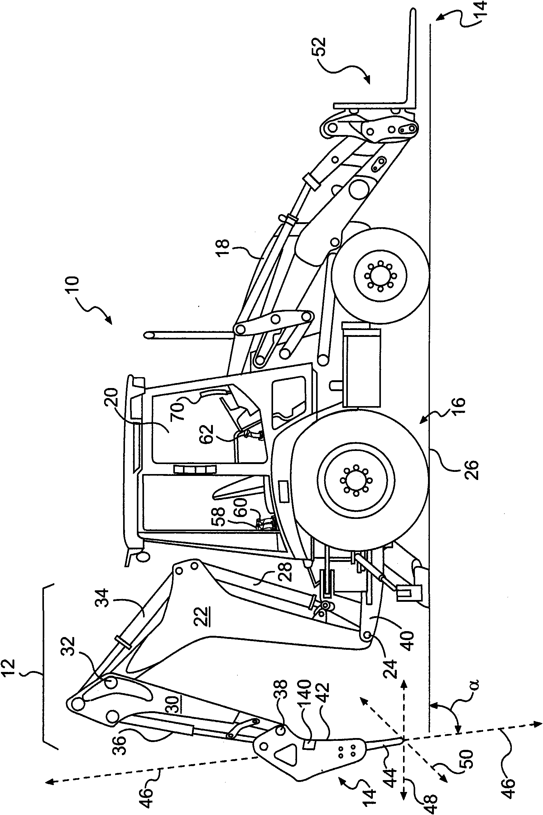
[0012] figure 1 An exemplary machine 10 is represented having multiple systems and components that cooperate to accomplish a task. Machine 10 may be embodied as a stationary or motorized machine that performs some type of operation associated with industries such as mining, construction, farming, transportation, or any other industry known in the art. For example, machine 10 may be an earth moving machine, such as a backhoe, excavator, bulldozer, loader, motor grader, or any other earth moving machine. The machine 10 may include an implement system 12 capable of moving the work tool 14, a drive system 16 for propelling the machine 10, a power source 18 for providing power to the implement system 12 and the drive system 16, and for an operator to control the implement system 12 and the drive system 16. The operating room 20 of the drive system 16 .

[0013] The power source 18 may be embodied as an engine, such as a diesel engine, a gasoline engine, a gaseous fuel driven engi...


PUM


Abstract

A tool control system is disclosed. The control system may have a first actuator (28) configured to control a first linkage (22). The control system may further have a second actuator (34) configured to control a second linkage (30). The control system may also have a third actuator (36) configured to control a work tool (14), wherein the second linkage is connected to the work tool and movably connected to the first linkage. The control system may still further have a plurality of operator input devices (58, 60) configured to provide operator control of the first, second, and third actuators. The control system may also have a controller (98) in communication with the first, second, and third actuators and the plurality of operator input devices. The controller may be configured to receive a desired tool path for the work tool. The controller may also be configured to control movement of the first, second, and third actuators based on operator input received from fewer than all of the plurality of operator input devices to move the work tool along the desired tool path.

Description

technical field [0001] The present invention relates generally to a control system, and more particularly to a control system that regulates the motion of a tool. Background technique [0002] Machines such as backhoes, excavators, bulldozers, loaders, motor graders, and other types of heavy equipment use a variety of actuators that supply hydraulic fluid from engine-driven pumps to accomplish a variety of tasks. Actuators, such as hydraulic cylinders and motors, are used to move linkage members and tools, such as booms, push rods, and buckets, on the machine. The operator controls the movement of the actuator by moving one or more input devices such as joysticks. Movement of the joystick manipulates the control valves associated with each actuator to control the movement of the boom and pushrod to position or orient the bucket to perform the task. Typical operator controls allow for individually controlled movement of each linkage member, eg, along a particular input devi...

Claims


Application Information

Patent Timeline
IPC IPC(8): E02F9/20E02F9/22E02F9/26E02F9/00
CPCE02F3/433E02F9/22E02F3/432E02F9/2045E02F9/2296E02F9/2037
Inventor R·D·科克D·F·斯塔尼克
Owner CATERPILLAR INC
Features
  • R&D
  • Intellectual Property
  • Life Sciences
  • Materials
  • Tech Scout
  • Unparalleled Data Quality
  • Higher Quality Content
  • 60% Fewer Hallucinations
Learn More