Lamp reflector and searchlight

A reflector and main reflector technology, applied in the field of lighting, can solve the problem of low light utilization rate of lamps and lanterns, and achieve the effect of increasing the irradiation distance and lighting brightness, and improving the utilization rate.

Inactive Publication Date: 2011-01-05
OCEANS KING LIGHTING SCI&TECH CO LTD +1
View PDF4 Cites 2 Cited by
  • Summary
  • Abstract
  • Description
  • Claims
  • Application Information

AI Technical Summary

Problems solved by technology

[0003] The object of the present invention is to provide a lamp reflector, aiming to solve the problem of low light utilization rate of traditional lamps

Method used


Image

  • Lamp reflector and searchlight
  • Lamp reflector and searchlight
  • Lamp reflector and searchlight

Examples


Embodiment 1

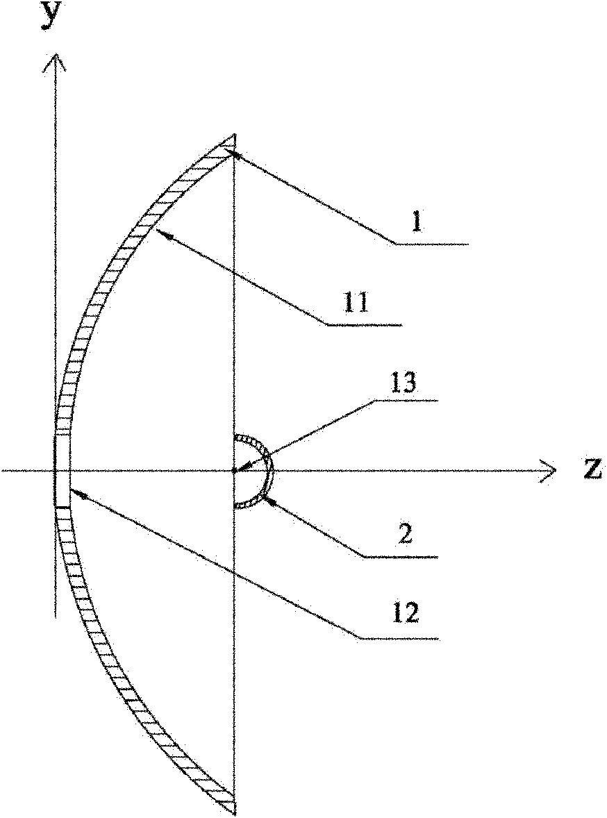
[0026] figure 2 A schematic structural view of the lamp reflector provided by the first embodiment of the present invention is shown, image 3 It shows the schematic diagram of the main reflector provided by the first embodiment of the present invention; Figure 4 A schematic diagram of the three-dimensional structure of the auxiliary reflector provided by the first embodiment of the present invention is shown, and for convenience of description, only parts related to this embodiment are shown.

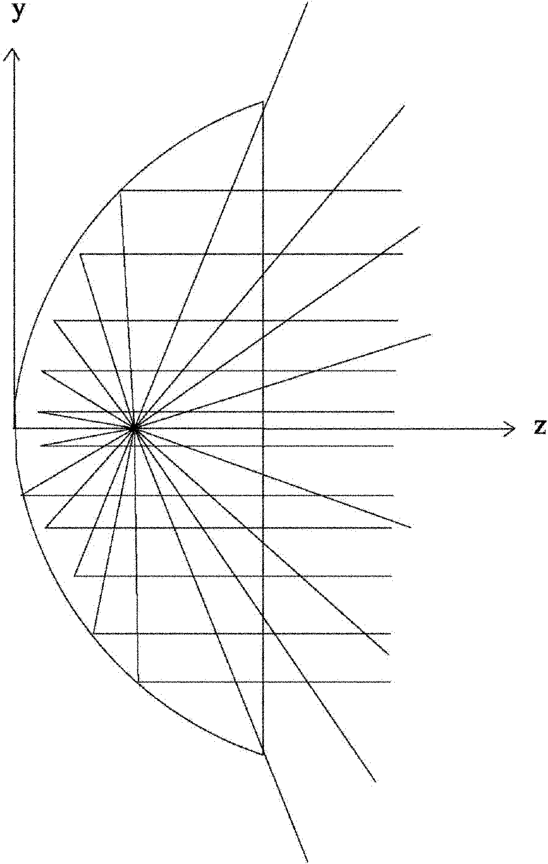
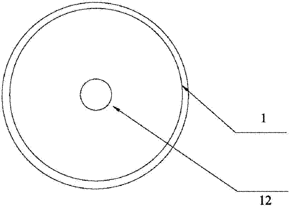
[0027] Please combine the attached figure 2 , 3 , the lamp reflector includes a main reflector 1 , and the inner surface of the main reflector 1 is a parabolic reflective surface 11 . At the bottom of the main reflector 1, there is a through hole around its central axis, that is, the first through hole 12. The first through hole 12 is used for the penetration of the light source. At the focal point 13 of the surface, the light emitted by the light source is reflected by the refl...

Embodiment 2

[0031] further combined with figure 2 , 5 , in the above embodiment, if the size of the auxiliary reflector 2 is too large, it will inevitably block part of the light, which is not conducive to remote lighting. Therefore, in the embodiment of the present invention, in order to use light more effectively, the size of the auxiliary reflector 2 is adjusted Properly controlled, the diameter of the opening is not larger than the size of the through hole 12 at the bottom of the main reflector 1, so as to ensure high light utilization.

Embodiment 3

[0033] further combined with figure 2 , 5 , in the embodiment of the present invention, the opening end of the main reflector 1 and the opening end of the auxiliary reflector 2 are just coplanar, so that the reflective surface 11 can be fully utilized. If the opening of the main reflector 1 extends outward for a certain length, the extended reflecting surface cannot receive and reflect light, which is a waste of raw materials, and reducing the length by a certain length will cause the light to emit from the edge. Therefore, it is most reasonable to arrange the opening ends of the main reflector 1 and the auxiliary reflector 2 on the same plane.


PUM


Abstract

The invention is applicable to the field of lighting, and provides a lamp reflector and a searchlight. The lamp reflector comprises a main reflector, wherein the main reflector comprises a parabolic reflecting surface; the bottom of the main reflector is provided with a first through hole through which a light source passes; a semispherical auxiliary reflecting mirror is arranged in the main reflector; the auxiliary reflecting mirror is arranged opposite to an opening of the main reflector, and central axes of the auxiliary reflecting mirror and the main reflector are overlapped; and the centre of sphere of the auxiliary reflecting mirror is overlapped with a focus of the reflecting surface. One semispherical auxiliary reflecting mirror is coaxially arranged in the conventional parabolic reflector, the centre of sphere of the auxiliary reflecting mirror is overlapped with the focus of the parabolic reflector, and original direct light is reflected along an original path through the auxiliary reflecting mirror and reflected back again at a small solid angle after passing through the focus of the parabolic reflector, so the utilization ratio of the light is improved, and the range of the lamp is expanded and the brightness of lighting is further improved.

Description

technical field [0001] The invention belongs to the lighting field, in particular to a lamp reflector and a searchlight. Background technique [0002] Most of the current lamps are equipped with reflectors. Common searchlights use reflectors to concentrate the outgoing beams in a small solid angle to obtain lamps with greater light intensity. as attached figure 1 As shown, the reflector of the searchlight is a parabolic reflector (that is, the reflector is a parabolic reflector). place. The disadvantage of this kind of lamp is that some light will be directly emitted without reflection, and its exit angle is too large to be fully utilized, which will cause the lamp's irradiation distance to be too small and the brightness not high. Contents of the invention [0003] The object of the present invention is to provide a lamp reflector, aiming to solve the problem of low light utilization rate of traditional lamps. [0004] The present invention is achieved in this way, a ...

Claims


Application Information

Patent Timeline
Patent Type & Authority Applications(China)
IPC IPC(8): F21V7/04F21V7/10F21V7/22F21S8/00F21V19/00
Inventor 周明杰陈涛
Owner OCEANS KING LIGHTING SCI&TECH CO LTD
Why Eureka
Try Eureka