
Idler gear for a generator

A generator and gear technology, applied in the field of gear sets, can solve problems such as uneven wear of gear teeth

Inactive Publication Date: 2011-01-05
HAMILTON SUNDSTRAND CORP
View PDF5 Cites 0 Cited by
  • Summary
  • Abstract
  • Description
  • Claims
  • Application Information

AI Technical Summary

Problems solved by technology

For example, axial misalignment of a gear may result in uneven wear of the gear teeth and eventual need for gear replacement

Method used


Image

  • Idler gear for a generator
  • Idler gear for a generator
  • Idler gear for a generator

Examples


Embodiment Construction

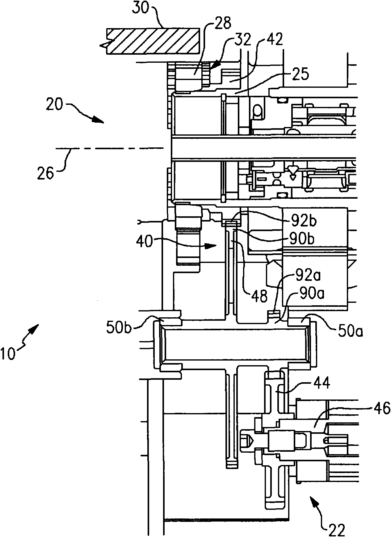
[0010] figure 1 Selected portions of an example generator 10 are shown. For example, generator 10 may be a variable frequency high-speed generator for starting a turbine engine and producing electrical current when driven by the turbine engine.

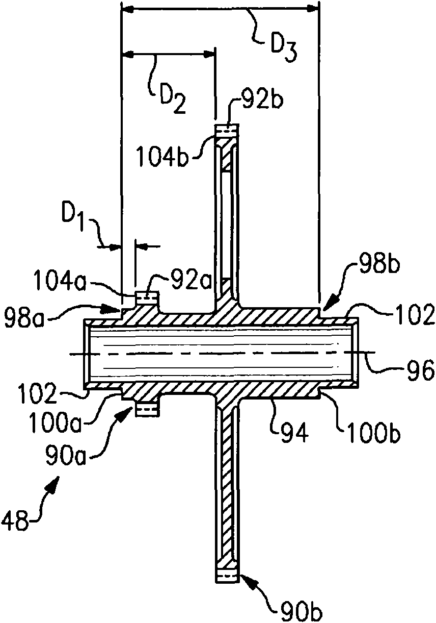
[0011] In the illustrated example, the generator 10 includes an electric portion 20 , a hydraulic pump 22 , and an idler gear or gear set 48 located between the hydraulic pump 22 and the electric portion 20 . The electric part 20 comprises a rotor shaft 25 rotatable about a central axis 26 . The rotor 28 is mounted on the rotor shaft 25 to be driven about the central axis 26 within the stator 30 (partially shown). The rotor 28 includes a plurality of magnetic members 32 , such as field coils or permanent magnets, spaced circumferentially about the rotor 28 relative to the central axis 26 . The general arrangement of motor generators is known and may vary from that shown in the illustrated example.

[0012] Generator 10 includes a ...


PUM


Abstract

The invention relates to an idler gear for a generator. A gear set for a generator includes a first gear having a first set of involute teeth and a second gear having a second set of involute teeth circumferentially located about a center axis of rotation. Each set of involute teeth includes respective roll angles, [epsilon]A-D. For a diametrically smaller one of the first gear and the second gear the roll angle [epsilon]A is 1.51 DEG -3.51 DEG , the roll angle [epsilon]B is 7.64 DEG -9.64 DEG , the roll angle [epsilon]C is 26.03 DEG -28.03 DEG , and the roll angle [epsilon]D is 32.16 DEG -34.16 DEG , and for a diametrically larger one of the first gear and the second gear the roll angle [epsilon]A is 15.02 DEG -17.02 DEG , the roll angle [epsilon]B is 16.7 DEG -18.7 DEG , the roll angle [epsilon]C is 21.73 DEG -23.73 DEG , and the roll angle [epsilon]D is 23.41 DEG -25.41 DEG.

Description

technical field [0001] The present invention relates to an improved gear set for controlling anticipated stresses within an electrical generator. Background technique [0002] Generators typically include a shaft driven for rotation and carrying a plurality of field coils or permanent magnets. The generator may also be used to drive a hydraulic pump, for example to cool the generator or other components in the system. A gear train may be used between the generator and the hydraulic pump. Misalignment of the gears within the gear train relative to the centerline of the shaft, bearings or other components can increase wear on the gears and contribute to reduced gear durability. For example, axial misalignment of a gear may cause uneven wear of the gear teeth and eventually require the gear to be replaced. Contents of the invention [0003] An exemplary gear set for a generator includes a first gear having a first set of involute gear teeth disposed circumferentially about...

Claims


Application Information

Patent Timeline
Patent Type & Authority Applications(China)
IPC IPC(8): H02K7/18
CPCH02K7/116H02K7/00H02K2213/03F16H55/0806F16H2055/0893F16H1/20Y10T29/49009Y10T74/19972
Inventor A·P·格罗斯科普夫E·A·布鲁斯特
Owner HAMILTON SUNDSTRAND CORP
Learn More