Lamp remote control method, lamp remote control switch and system thereof

A technology of remote control switch and remote control system, applied in signal transmission system, energy-saving control technology, lamp circuit layout, etc. The effect of wiring

Inactive Publication Date: 2011-01-05
深圳市金通慧网络技术有限公司
View PDF2 Cites 20 Cited by
  • Summary
  • Abstract
  • Description
  • Claims
  • Application Information

AI Technical Summary

Problems solved by technology

[0004] However, the common remote control switch has the following problems because it must be controlled by a remote control: First, there is a one-way data transmission between the controlled switch and the remote control, which is only suitable for one-way centralized control and cannot meet the needs of interaction. Distributed multi-point mutual control cannot form a control system with more than a dozen control points; second, the remote control needs to be powered by batteries and needs to be replaced, which is not suitable for general promotion in the family; third, the remote control is easy to lose and cannot It is suitable for multi-person use; fourth, the remote control does not conform to the usual switch operation and installation mode; fifth, the remote control needs to install batteries, so its power is limited, and it is not suitable to use night light instructions
[0005] The existence of the above problems prevents the remote control switch from being widely used in the past. It can only be said to be an extension of the traditional switch, not a change.

Method used


Image

  • Lamp remote control method, lamp remote control switch and system thereof
  • Lamp remote control method, lamp remote control switch and system thereof
  • Lamp remote control method, lamp remote control switch and system thereof

Examples


Embodiment Construction

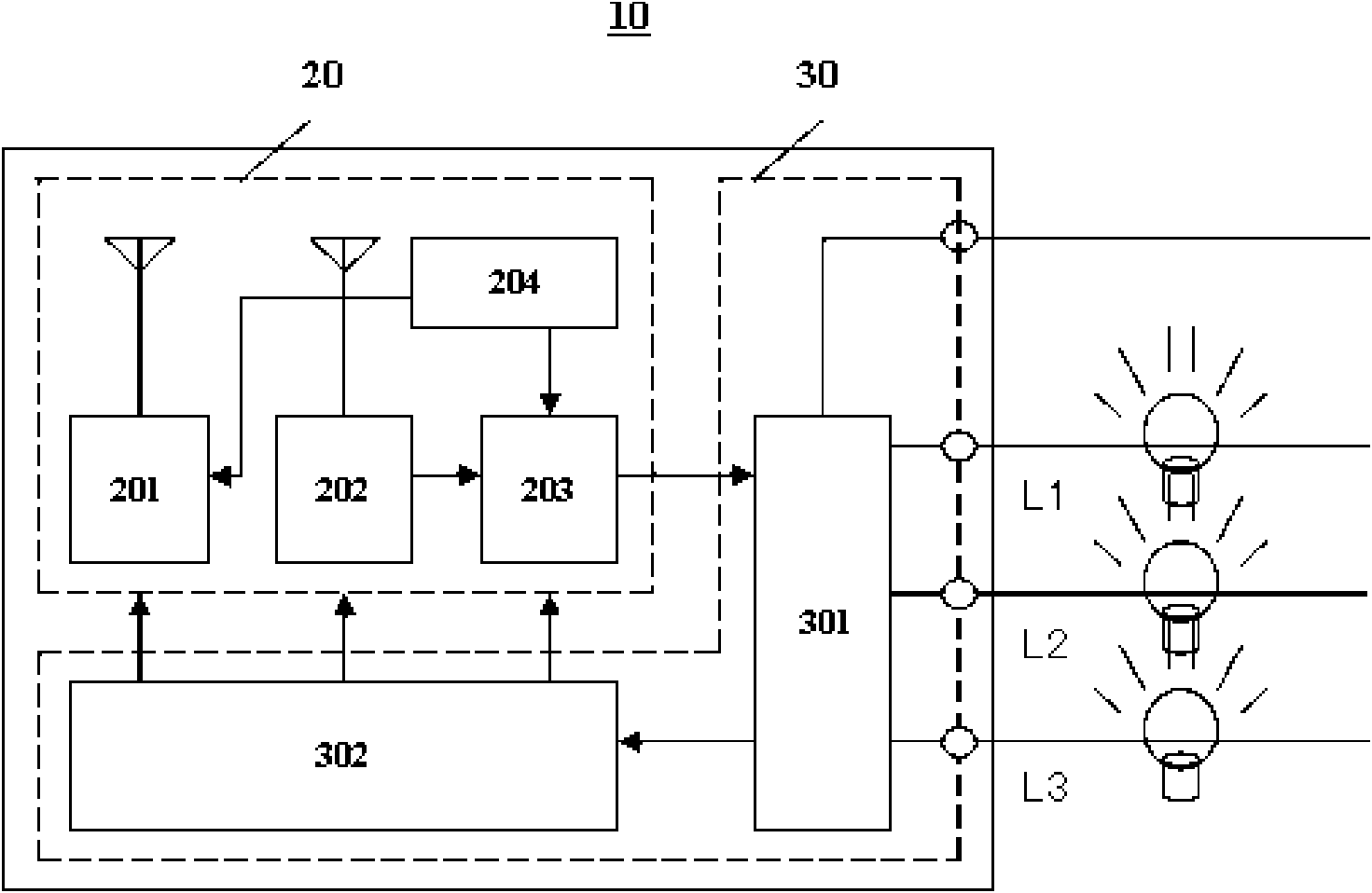
[0025] see figure 1 , is a schematic diagram of the circuit structure of a preferred embodiment of the remote control switch for lamps and lanterns of the present invention. The lamp remote control switch 10 can be installed on a wall, and includes a control unit 20 and a power supply unit 30 . The control unit 20 can receive and send signals at the same time, and the power supply unit 30 is used to supply power to the lamp remote control switch 10 and control external lamps.

[0026] The control unit 20 includes a transmitting circuit 201 , a receiving circuit 202 , a control circuit 203 and a backlight circuit 204 . The transmitting circuit 201 and the receiving circuit 202 are low-power transmitting circuits and low-power receiving circuits. The power supply unit 30 includes a relay group 301 and a power taking circuit 302, and the power taking circuit 302 is a single live wire power taking circuit. The emission circuit 201 is connected to the backlight circuit 204 . Th...


PUM


Abstract

The invention relates to a lamp wireless mutual control switch which comprises a control unit and a power supply unit, wherein the control unit includes a transmitting circuit used for transmitting wireless RF signals according to an outer instruct and a receiving circuit used for receiving the wireless RF signals, the power supply unit controls opening or close of an external lamp according the signals received by the receiving circuit, and has single live wire accession without null line accession; and the control unit also includes a backlight circuit used for providing noctilucence display for the lamp wireless mutual control switch. The invention also provides a lamp mutual control system. The lamp wireless mutual control switch and the system have the beneficial effect that a total standby power dissipation current is 40-75 microamps, this index enables that the lamps such as energy saving lamps, the LED lamps or the like do not flicker so as to suit different lamps under the conduction that the single live wire switch and loads are tandem.

Description

technical field [0001] The invention relates to a lamp remote control method, a switch and a system using the lamp remote control method, in particular to a single-wire wireless transceiver mutual control switch and system. Background technique [0002] A general remote control switch is composed of a controlled wall switch and a matching remote control. The remote control sends control commands, and the controlled wall switch receives control commands through the receiving device and executes the operation commands, so that a single remote control can control multiple Controlled wall switch. [0003] The wireless remote control switch, especially the wireless remote control switch with the characteristics of single live wire in and out and low power consumption that has appeared in recent years, directly replaces the 86-type mechanical wall switch, free of wiring, and suitable for various loads. Therefore, in some occasions where remote partition remote control must be use...

Claims


Application Information

Patent Timeline
Patent Type & Authority Applications(China)
IPC IPC(8): H05B37/02G08C17/02
CPCY02B20/42Y02B20/40
Inventor 张玉良
Owner 深圳市金通慧网络技术有限公司
Why Eureka
Try Eureka