Supercharge Your Innovation With Domain-Expert AI Agents!

Luminescent module, and its manufacturing method

A light-emitting component and manufacturing method technology, applied in the direction of electrical components, semiconductor devices, electric solid devices, etc., can solve the problems of sealing resin peeling, insufficient adhesion, and inability to fully dissipate heat, and achieve the goal of reducing the number of parts and reducing costs Effect

Inactive Publication Date: 2011-01-05
SANYO ELECTRIC CO LTD +2
View PDF1 Cites 4 Cited by
  • Summary
  • Abstract
  • Description
  • Claims
  • Application Information

AI Technical Summary

Problems solved by technology

Therefore, when a high-brightness LED through which a high current of 200 mA or more flows is used as the light-emitting element 15 to emit light, the structure described in Japanese Patent Application Laid-Open No. 2006-100753 may not be able to dissipate heat sufficiently.
[0006] In addition, since the sealing resin used to seal the light-emitting element 15 does not have sufficient adhesion to other members (such as the substrate), there is a risk that the sealing resin will peel off from the substrate due to thermal stress caused by temperature changes during use.

Method used


Image

  • Luminescent module, and its manufacturing method
  • Luminescent module, and its manufacturing method
  • Luminescent module, and its manufacturing method

Examples


Embodiment Construction

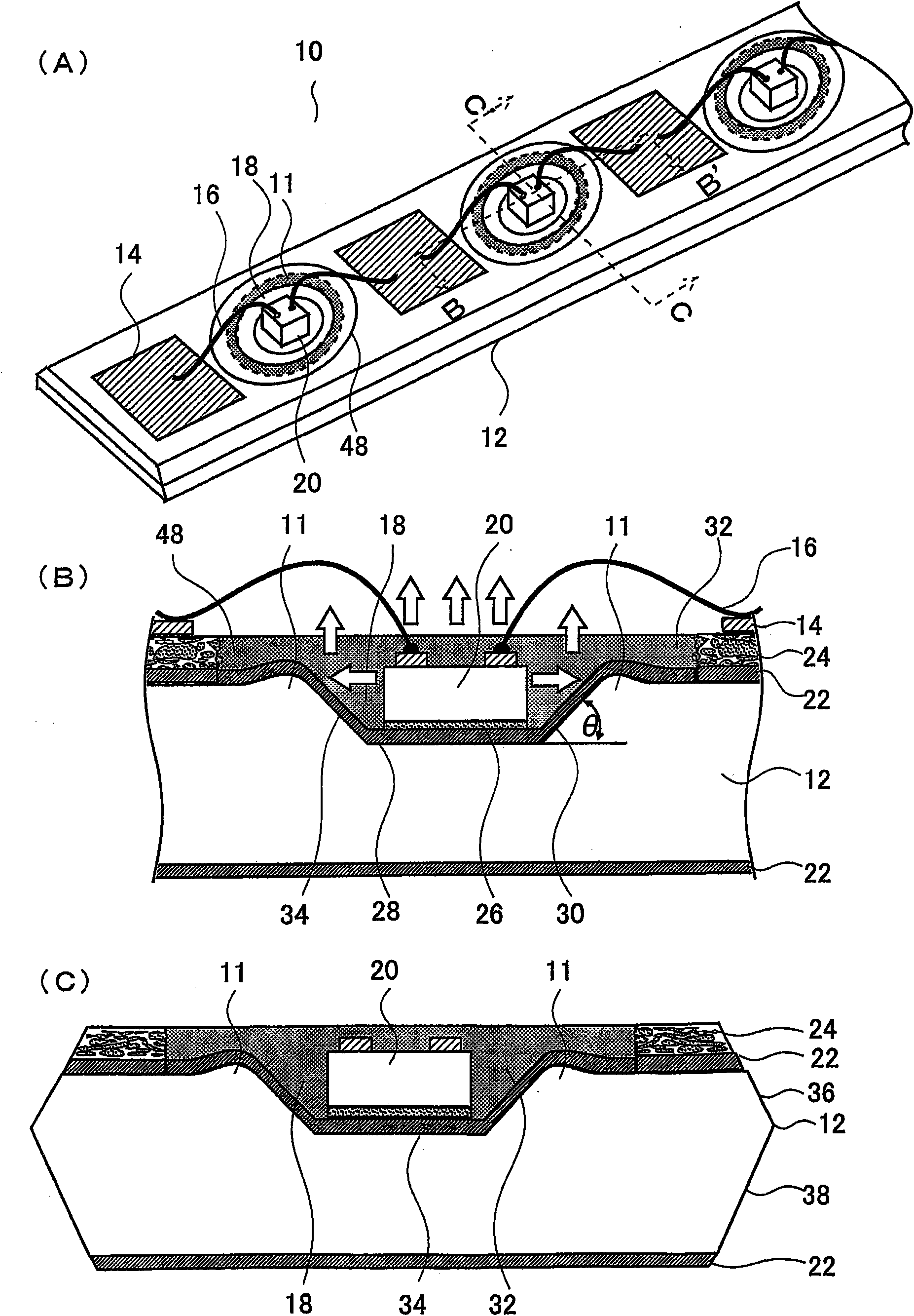
[0055] refer to figure 1 The structure of the light emitting module 10 of the present invention will be described. figure 1 Among them, (A) is a perspective view of the light emitting module 10, (B) is a cross-sectional view of line B-B' of (A), and (C) is a cross-sectional view of line C-C' of (A).

[0056]Referring to these drawings, the light-emitting assembly 10 mainly includes a metal substrate 12, a conductive pattern 14 formed on the upper surface of the metal substrate 12, a concave portion 18 formed by making a part of the upper surface of the metal substrate 12 concave, and the surrounding area of ​​the concave portion 18. The upper surface of the metal substrate 12 has a convex portion 11 formed in a convex shape, a light emitting element 20 housed in the concave portion 18 , and a sealing resin 32 covering the light emitting element 20 .

[0057] refer to figure 1 (A), the light emitting module 10 has a plurality of light emitting elements 20 mounted on the up...


PUM


Abstract

Provided are a luminescent module, which is improved in the heat radiation and in the contact between a sealing resin for sealing a light emitting element and another member, and a method for manufacturing the module. The luminescent module (10) comprises a metal substrate (12), a recess (18) formed by recessing the upper face of the metal substrate (12) partially, a light emitting element (20) housed in the recess (18), and a sealing resin (32) for covering the light emitting element (20). On the upper face of a metal substrate (40) in the region enclosing the recess (18), moreover, there is formed a rising portion (11), with which the sealing resin (32) comes into contact, thereby to improve the contact strength between the sealing resin (32) and the metal substrate (12).

Description

technical field [0001] The invention relates to a light-emitting component and a manufacturing method thereof, in particular to a light-emitting component equipped with a high-brightness light-emitting element and a manufacturing method thereof. Background technique [0002] Semiconductor light-emitting devices represented by LEDs (Light Emitting Diodes) have been used in traffic signals and automobile lights due to their long service life and high visibility. In addition, LEDs have also been used as lighting equipment. [0003] When LEDs are used as lighting equipment, brightness is not enough with only one LED, so many LEDs are mounted in one lighting equipment. However, LEDs dissipate a large amount of heat when they emit light. Therefore, after mounting the LEDs on a mounting substrate made of a resin material with poor heat dissipation, or encapsulating each LED with resin, the heat dissipated from the LEDs may not be sufficient. The problem of premature degradation o...

Claims


Application Information

Patent Timeline
Patent Type & Authority Applications(China)
IPC IPC(8): H01L33/00H01L33/32H01L33/56H01L33/60H01L33/62H01L33/64
CPCH01L33/60H01L24/97H01L2224/48091H01L2224/8592H01L33/54H01L2224/73265H01L2933/0058H05K1/056H01L2224/48465H05K1/021H01L25/0753H01L2924/07802H01L2924/12041H01L2924/351H01L2924/00H01L2924/00014
Inventor 高草木贞道本池达也松本章寿
Owner SANYO ELECTRIC CO LTD
Features
  • R&D
  • Intellectual Property
  • Life Sciences
  • Materials
  • Tech Scout
  • Unparalleled Data Quality
  • Higher Quality Content
  • 60% Fewer Hallucinations
Learn More