Light-emitting sign device

a technology of light-emitting signs and signs, which is applied in the direction of illuminated signs, display means, instruments, etc., can solve the problems of difficult to obtain uniform incident light on the sign surface, degrade visibility, uneven light emission, etc., and achieve no light loss, no decrease in intensity, and uniform intensity

Inactive Publication Date: 2009-01-29
TAMURA KK +1
View PDF0 Cites 12 Cited by
  • Summary
  • Abstract
  • Description
  • Claims
  • Application Information

AI Technical Summary

Benefits of technology

[0012]In accordance with the invention having the above-described features, the light guide member transmits the light from the light source to every corner of the light guide member. In this case, since the light-scattering layer is formed between the reflecting member and light guide member, the light of the light source that is incident on the light guide member is scattered by the light-scattering layer in the direction ensuring light uniformity on the reflecting member, and this light is reflected by the reflecting member toward the light-scattering layer. Therefore, the light is repeatedly scattered and reflected between the light-scattering layer and reflecting member and then taken out from the light guide member. For this reason, the light emitted from the light guide member has uniform intensity, no light loss, and no decrease in intensity. As a result, the sign member can be efficiently illuminated with the light from the light guide member, and this causes the sign member to emit uniform and bright light.
[0013]With the light-emitting sign device in accordance with the present invention, by using a very simple feature of a light-scattering layer formed between a reflecting member and a light guide member, it is possible to reduce light loss to a minimum, while ensuring optimum scattering of light from a light source, enable uniform and bright emission, and improve visibility and cost efficiency.

Problems solved by technology

Therefore, the light-emitting sign devices of an edge light type excel in cost efficiency and convenience, but since the light of the light source is incident on the sign surface of the sign member from the side thereof, light emission is uneven.
In other words, in the light-emitting sign devices of an edge light type, it is difficult to obtain a uniform incident light on the sign surface from the light of the light source provided on the side of the sign member.
As a result, the occurring emission unevenness degrades visibility.
However, the conventional light-emitting sign devices have been shown to have the following problems.
As a result, sufficient brightness cannot be obtained and visibility is decreased.
Therefore, light source output had to be increased to maintain visibility, thereby increasing cost.

Method used


Image

  • Light-emitting sign device
  • Light-emitting sign device

Examples


Embodiment Construction

[Typical Configuration of Embodiment]

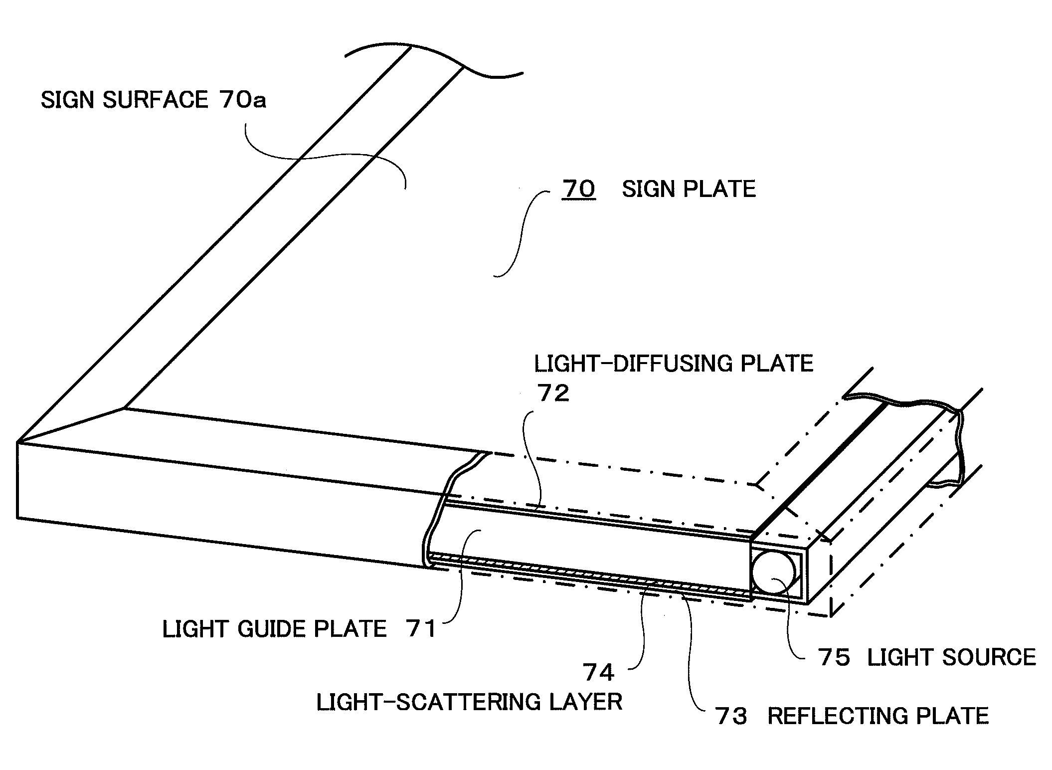
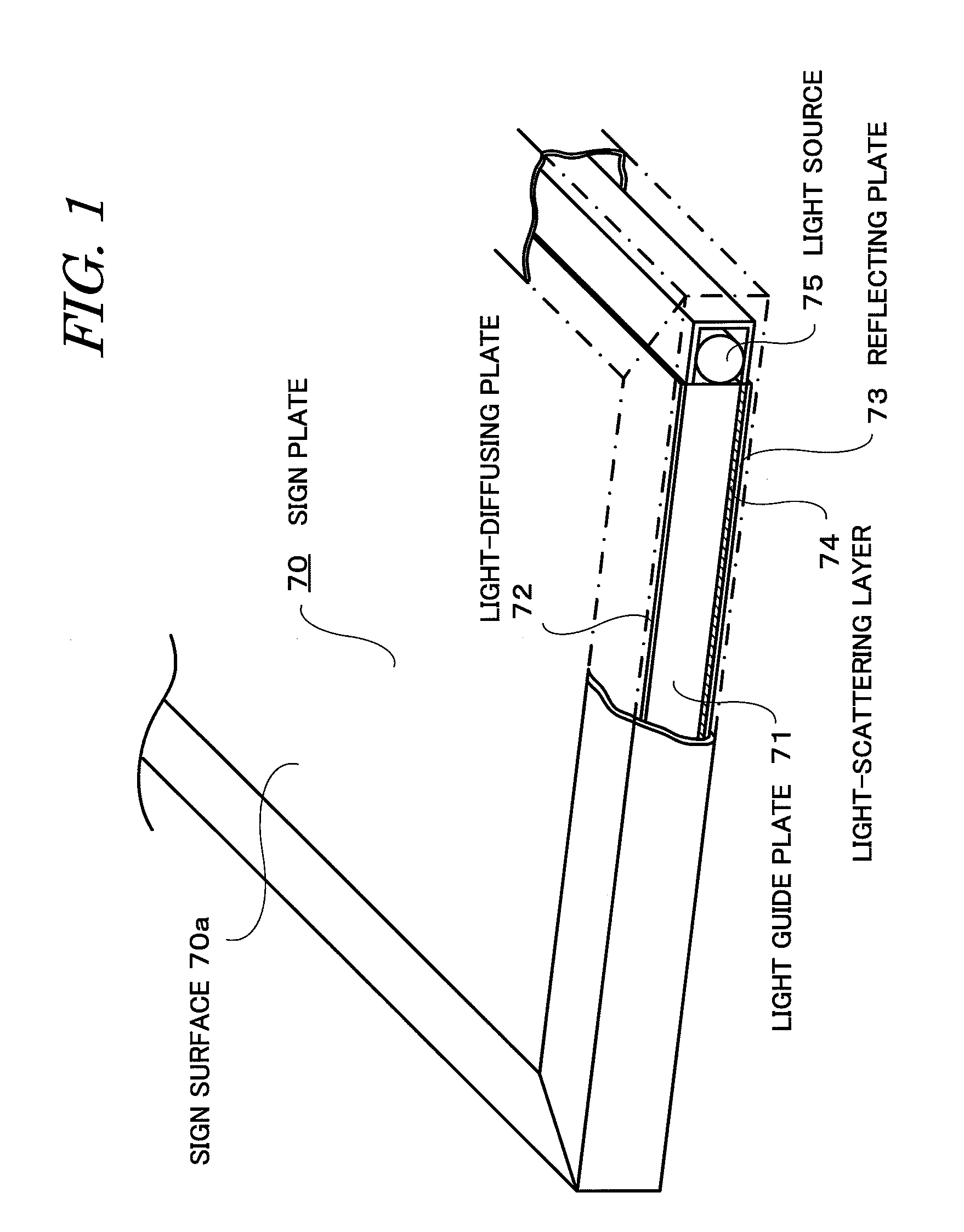
[0015]The best modes for carrying out the invention (referred to hereinbelow as “embodiments”) will be described below in detail with reference to the appended drawings. FIG. 1 is a perspective view illustrating the configuration of the present embodiment.

[0016]As shown in FIG. 1, the light-emitting sign device of the present embodiment is a light-emitting sign device of an edge light type in which a light source 75 is provided close to both side edge portions on short sides of a rectangular sign plate 70 having long sides and the short sides, wherein the sign plate 70 having a sign surface 70a is provided, and a light-diffusing plate 72, a light guide plate 71, and a white reflecting plate 73 are arranged in this order on the rear side of the sign plate. A specific feature of the present embodiment is that a light-scattering layer 74 that scatters light from the light source 75 is formed by coating on the rear surface of the light guide plate 71...


PUM


Abstract

A light-emitting sign device is provided, in which optimum scattering of light from a light source is ensured, light loss can be reduced to a minimum, uniform and bright emission is made possible, and visibility and cost efficiency are improved. A sign plate having a sign surface is provided, and a light-diffusing plate, light guide plate, and white reflecting plate are arranged in this order on the rear surface of the sign plate. A light-scattering layer that scatters the light from the light source is coated on the rear surface of the light guide plate. The light-scattering layer has a binder layer composed of a coating composition using a transparent resin as a binder. A filler in the form of transparent and substantially spherical fine particles of silica is uniformly dispersed in the binder layer.

Description

BACKGROUND OF THE INVENTION[0001]1. Field of the Invention[0002]The present invention relates to a light-emitting sign device of an edge light type in which surface emission from a sign member is performed, and more particularly to a light-emitting sign device improved so as to ensure uniform light emission from a sign member.[0003]2. Description of the Related Art[0004]Sign members such as marks or signboards for stores or advertisement are required to demonstrate high visibility so that they can be readily recognized even at night. For this purpose, there are sign device that illuminate the sign members with a projector from the front surface and light-emitting sign devices in which a light source is mounted on the rear surface of the sign member to cause surface emission from the sign member. Among these devices, in the light-emitting sign devices of an edge light type, a light source is provided close to the side edge portion of the sign member, and since the light source is pro...

Claims


Application Information

Patent Timeline
Patent Type & Authority Applications(United States)
IPC IPC(8): G09F13/18
CPCG02B6/0051G09F13/18G02B6/0055
Inventor DAIMON, SUEYOSHINARUSE, TSUNEHIDESUZUKI, YUKIHARU
Owner TAMURA KK
Why Eureka
Try Eureka