Display device, terminal device, display panel, and optical member

a technology of display panel and display panel, which is applied in the direction of optics, instruments, optical light guides, etc., can solve the problems of inability to see the observer's right eye, blockage of pixels for displaying the left-eye image, and inconvenient eyeglasses in these systems, so as to minimize the reduction in the quality of transmissive display, increase image quality, and increase image quality

Active Publication Date: 2008-04-24
NEC LCD TECH CORP
View PDF9 Cites 52 Cited by
  • Summary
  • Abstract
  • Description
  • Claims
  • Application Information

AI Technical Summary

Benefits of technology

[0016] A second object of the present invention is to provide a display device capable of minimizing a reduction in the quality of a transmissive display and achieving increased image quality without changing the concavo-convex structure formed in the illumination member and the lens shape of the lenticular lens, to provide a terminal device, to provide a display panel, and to provide an optical member.
[0017] A third object of the present invention is to provide a display device capable of achieving increased image quality and minimizing a reduction in image quality that is caused by the pattern of regions that do not contributed to the display being observed as lines that are parallel to the arrangement direction of the lenses and slits, to provide a terminal device, to provide a display panel, and to provide an optical member.
[0018] The present invention is characterized in that an anisotropic scattering part is provided to the display device, whereby it is possible to minimize a reduction in the quality of the image displayed using the image separating optical means and the display panel, without dramatically compromising the image separating effect of the lens, the barrier, or other image separating optical means. In order to achieve this, an anisotropic scattering part is preferably provided for scattering light that is incident or excident with respect to the pixels of the display panel so that the scattering in the image separation direction is different from scattering in other directions. As a result, not only is it possible to prevent a reduction in the display image quality, but costs can be reduced because the structure of the image allocation part and the display panel need not be changed.
[0019] In particular, the direction of maximum scattering by the anisotropic scattering part is the direction orthogonal to the image separation direction, whereby the image quality can be improved without compromising the image separation effect of the image separation optical means. The anisotropic scattering part is preferably disposed on the image separation means side of the display panel pixels. In this case, in combination with a display panel having a reflecting plate in pixels, deterioration in image quality is minimized by the image allocation part and the concavo-convex structure formed on the reflecting plate, and the image quality of the reflection display can be improved. In combination with a semi-transmissive or [fully] transmissive display panel, it is possible to reduce any deterioration in image quality due to the combination of the image allocation part and the boundary of adjoining pixels, and to improve image quality.
[0020] According to the display device of the present invention, furthermore, the direction of maximum scattering of the anisotropic scattering part can be the first direction, where the pixel for displaying an image for the first viewpoint and the pixel for displaying an image for the second viewpoint are arranged in the display unit. The image allocation part allocates light emitted from the pixels to different directions along a first direction. In this case, the anisotropic scattering part is disposed on the rear side of the display panel, thereby maximizing the effect of arresting deterioration in image quality caused by the anisotropic scattering part. It is also possible to increase image quality particularly in the case that a planar light source for emitting light in a plane is provided to the rear side of the display panel. This is because light is emitted in a plane via the concavo-convex structure formed on the surface and interior of the planar light source, but the present invention is able to minimize any deterioration in display quality due to the concavo-convex structure of the planar light source and the image allocation part. Moreover, the use of the anisotropic scattering part enables the scattering direction to be limited, and any decrease in frontal luminance can accordingly be minimized.
[0021] According to the present invention, in a display device to which a lenticular lens and a parallax barrier or other optical member for image allocation is provided, an anisotropic scattering part is provided that produces greater scattering in the direction orthogonal to the image allocation direction of the optical member in the display plane than the scattering in the image allocation direction. The effects of the concavo-convex structure formed on the reflecting panel can thereby be reduced, and image quality can be improved. The effects of the concavo-convex structure formed on the illumination member can also be reduced, and image quality can be improved. Furthermore, the effects of non-display regions that are observed as line segments parallel to the image allocation direction can be reduced, and image quality can be improved.

Problems solved by technology

Systems that use eyeglasses include anaglyph systems that use a color difference, polarized-light eyeglass systems that use polarized light, and other systems, but the inconvenience of eyeglasses is inherent to these systems.
As a result, the pixels for displaying the left-eye image are blocked by the barrier and unable to be seen by the observer's right eye, and only the pixels for displaying the right-eye image are visible to the observer's right eye.
When the parallax barrier system was first proposed, the parallax barrier was positioned between the pixels and the eyes, thereby obstructing the view and creating the problem of poor visibility.
However, the present inventors have discovered that several problems occur when an optical member is merely provided, and the inventors have proposed means for overcoming these problems.
The cause of this problem is that the reflection angle varies according to the tilt angle of the tilted surfaces that constitute the concavo-convex structure when external light that is focused by the lenticular lens is reflected by the concavo-convex structure formed on the reflecting panel.
As described in Japanese Laid-open Patent Application No. 2006-17820, another problem that occurs when an optical member is provided is that a fringe pattern is superimposed on the display image, and display quality is severely reduced by the effect of the concavo-convex structure formed in the illumination member of the transmissive display device when an optical member used for image separation is incorporated into a transmissive display device.
The cause of this problem is that an in-plane distribution occurs in the directivity of light rays emitted from the illumination member due to the concavo-convex structure that is formed in the illumination member, and this in-plane distribution is visibly magnified by the optical member for image separation.
This problem is exacerbated as the concavo-convex structure of the illumination member is brought closer to the focal plane of the lenticular lens by profile reduction and the like.
However, such problems as the following are apparent in the methods described above for overcoming the issues described above, i.e., the reduction in display quality caused by the concavo-convex structure formed in the reflecting panel, or the image quality reduction due to the concavo-convex structure formed in the illumination member, by varying the performance of the concavo-convex structure or the lenticular lens.
Specifically, problems occur in that the lens or other optical element, as well as the concavo-convex structure of the reflecting panel, and the concavo-convex structure of the illumination member must be changed.
There may be no options for modification particularly when a common, standardized product is used for the members described above.
As a result of concentrated investigation of display devices provided with a lenticular lens, a parallax barrier, or other optical member, the inventors discovered that the pattern of boundary regions between adjacent pixels or other regions that do not contribute to the display in these display devices is observed as parallel lines in the arrangement direction of the lenses or slits, and that the problem of reduced image quality occurs.

Method used


Image

  • Display device, terminal device, display panel, and optical member
  • Display device, terminal device, display panel, and optical member
  • Display device, terminal device, display panel, and optical member

Examples


embodiment 1

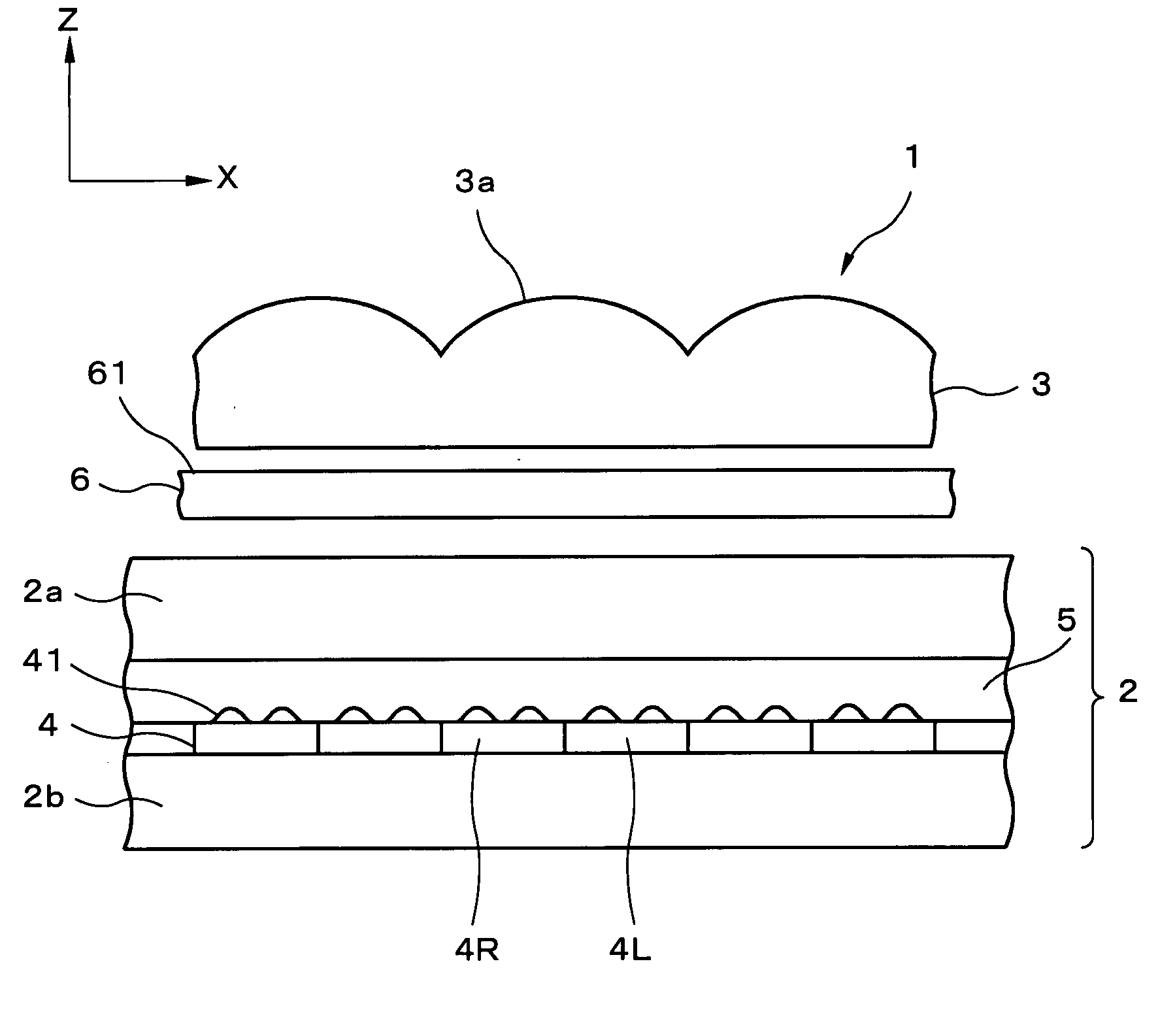
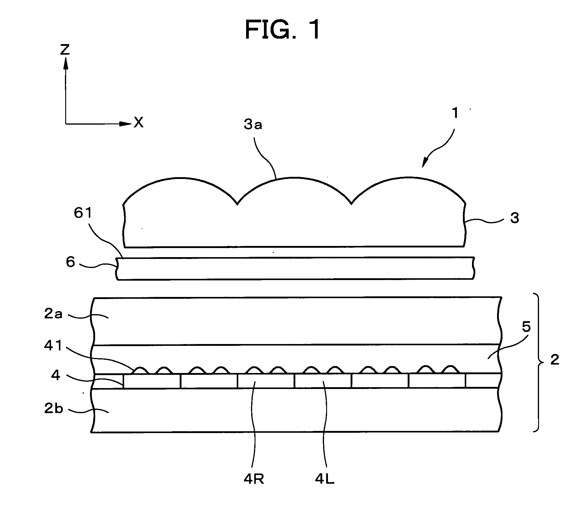
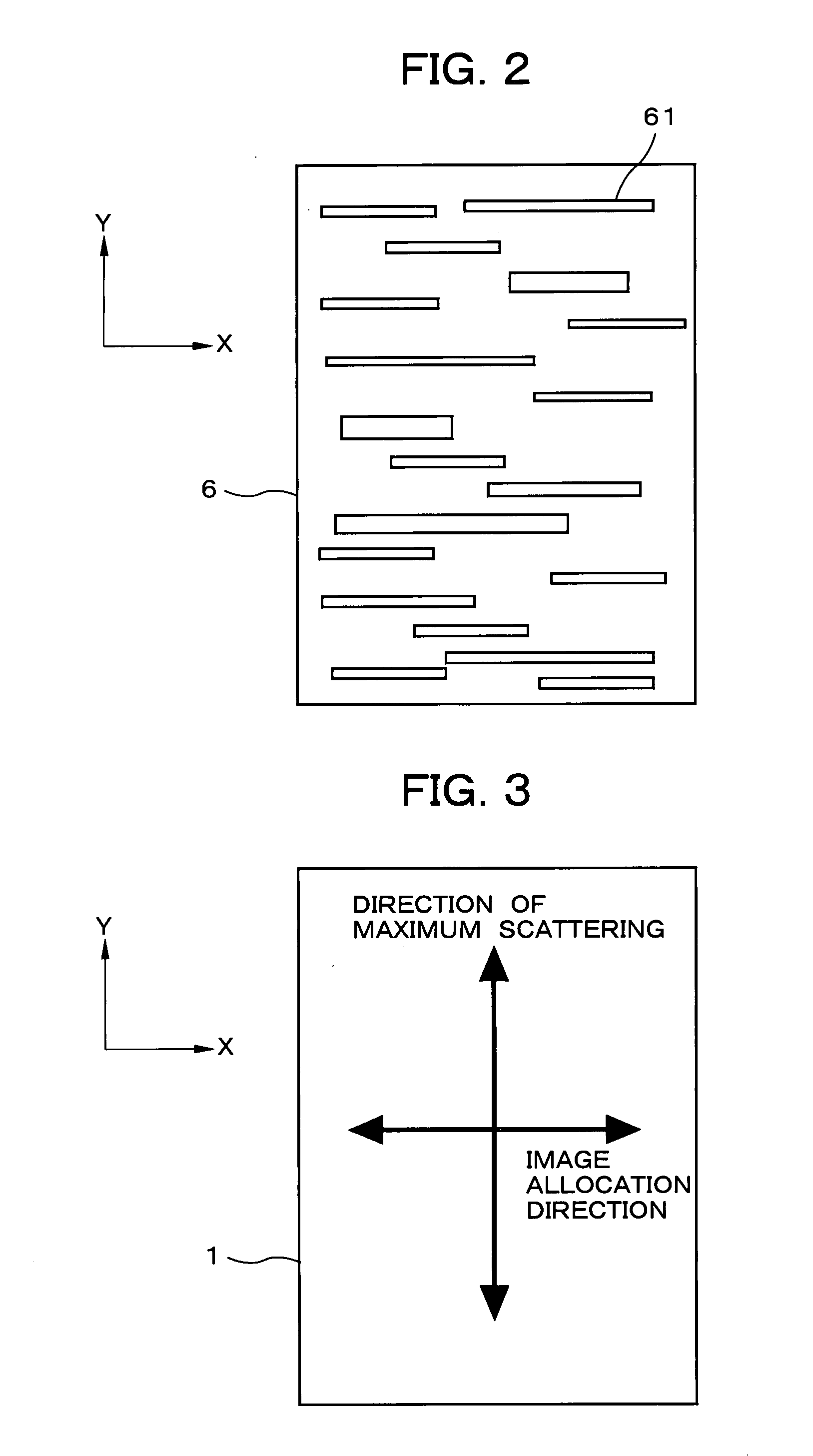
[0110] Next, the display device, terminal device, display panel, and optical member according to embodiments of the present invention will be specifically described hereinafter with reference to the accompanying drawings. The display device, terminal device, display panel, and optical member of the present invention will first be described. FIG. 1 is a sectional view showing the display device according to the present embodiment; FIG. 2 is a top view showing the anisotropic scattering sheet shown in FIG. 1; FIG. 3 is a top view showing the relationship between the image allocation direction of the image allocation part, and the scattering direction of the anisotropic scattering sheet in the display device shown in FIG. 1; and FIG. 4 is a perspective view showing the terminal device of the present embodiment.

[0111] As shown in FIG. 1, the display device according to Embodiment 1 uses a reflective liquid crystal display panel 2 as the display panel, and the reflective liquid crystal ...

embodiment 2

[0169] Specifically, in the reflective liquid crystal display device 12 of the present embodiment as shown in FIG. 17, the anisotropic scattering glue 63 is applied to the surface opposite the surface on which the cylindrical lenses 3a of the lenticular lens 3 are formed, and the lenticular lens 3 and the reflective liquid crystal display panel 2 are affixed together by the anisotropic scattering glue 63. The anisotropic scattering glue 63 is a glue in which materials that are worked into fibers or rod shapes are oriented and dispersed, and the materials each have different refractive indices, for example. Aspects of the present embodiment other than those described above are the same as in

[0170] In the present embodiment, the use of the anisotropic scattering part makes it possible to prevent a reduction in display quality due to the lenticular lens and the concavo-convex structures of the reflecting panel without significantly compromising the image allocation effects of the lenti...

embodiment 3

[0172] Specifically, in the reflective liquid crystal display device 13 of the present embodiment as shown in FIG. 8, the base material of the lenticular lens 32 has anisotropic scattering, whereby the lenticular lens 32 itself has anisotropic scattering capability. Suitable methods that can be used to fabricate a base material having anisotropic scattering capability include a method for orienting and dispersing fibrous or rod-shaped materials having different refractive indices when the base material is fabricated, a method for extending a base material that has isotropic scattering so as to make the scattering anisotropic, and other methods. A hot embossing method, for example, may be used to transfer a lens shape to a base material having anisotropic scattering capability that is fabricated according to the aforementioned methods in order to fabricate a lenticular lens 32 that has anisotropic scattering. The lenticular lens 32 is fixed to the reflective liquid crystal display pa...


PUM


Abstract

A reflective liquid crystal display panel is a display panel for three-dimensional display in which pixel pairs as display elements composed of one left-eye pixel L and one right-eye pixel R each are provided in a matrix. The lenticular lens is an optical member for image separation that is provided to separate the light from the left and right pixels, and numerous lenticular lenses form a lens array that is arranged in one dimension. An anisotropic scattering sheet as an anisotropic scattering element is provided between the lenticular lens and the reflective liquid crystal display panel. According to this configuration, a reduction in the quality of the reflective display can be minimized, and improved image quality can be achieved without changing the concavo-convex structure of the reflecting panel and the lens shape of the lenticular lens in display device that is capable of displaying different images to a plurality of viewpoints.

Description

BACKGROUND OF THE INVENTION [0001] 1. Field of the Invention [0002] The present invention relates to a display device capable of displaying an image toward each of a plurality of viewpoints, and to a terminal device, and particularly relates to a display device capable of reducing a deterioration in display quality due to the structure of the display device, to a terminal device, and to a display panel and optical member that can be suitably used in the display device and terminal device. [0003] 2. Description of the Related Art [0004] Due to recent technological development, display panels are deployed and used in various locations in a range of devices that includes monitors, television receivers, and other large terminal devices; notebook personal computers, cash dispensers, vending machines, and other mid-sized terminal devices; and personal TVs, PDAs (Personal Digital Assistance: personal information terminal), mobile phones, mobile gaming devices, and other small terminal devi...

Claims


Application Information

Patent Timeline
Patent Type & Authority Applications(United States)
IPC IPC(8): G02B27/22
CPCG02B3/0025G02B27/2214G02B5/0257G02B3/0056G02B6/0043G02B6/0051G02B6/0053G02B6/0061G02F1/133526G02F1/133615G02F2202/28G02F2203/01G02F2203/02G02B30/27H04N13/305H04N13/31
Inventor UEHARA, SHIN-ICHI
Owner NEC LCD TECH CORP
Why Eureka
Try Eureka