Breadth edge-cutting device

A technology of edge trimming and width, applied in metal processing and other directions, can solve the problems of easy jamming, high labor intensity, troublesome operation, etc., and achieve the effect of avoiding jamming, reducing labor intensity and simple operation

Active Publication Date: 2011-01-12
JIANGSU VICTORY MACHINERY
View PDF7 Cites 31 Cited by
  • Summary
  • Abstract
  • Description
  • Claims
  • Application Information

AI Technical Summary

Problems solved by technology

In actual use, when adjusting the width (adjusting the lateral distance between the cutters), both ends need to be adjusted separately, that is: adjust the cutter mechanism 1 on the left through the distance adjustment handwheel 3 on the left, and adjust the cutter mechanism 1 on the left through the distance adjustment hand wheel on the right. Adjust the distance adjustment handwheel 4 to adjust the cutter mechanism 2 on the right side; when lowering the knife, two people need to adjust the lower knife handwheel 5 on the left and the lower knife handwheel 6 on the right at the same time. If the speed or distance is different, the pair of transverse guide rods 7 and 8 will be tilted, and the pair of vertical moving plates 9 and 10 and the corresponding pair of vertical guide rods 11 and 12 will be easily stuck, so the operation must be very careful, so that the operation The staff is very tiring and the labor intensity is high
In summary, the operation of this width cutter device is very troublesome and the work efficiency is low

Method used


Image

  • Breadth edge-cutting device
  • Breadth edge-cutting device
  • Breadth edge-cutting device

Examples


Embodiment Construction

[0017] Specific embodiments of the present invention will be described in detail below in conjunction with the accompanying drawings.

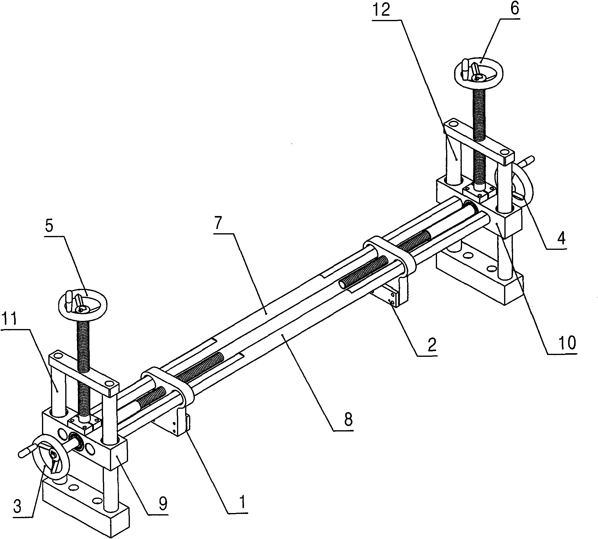
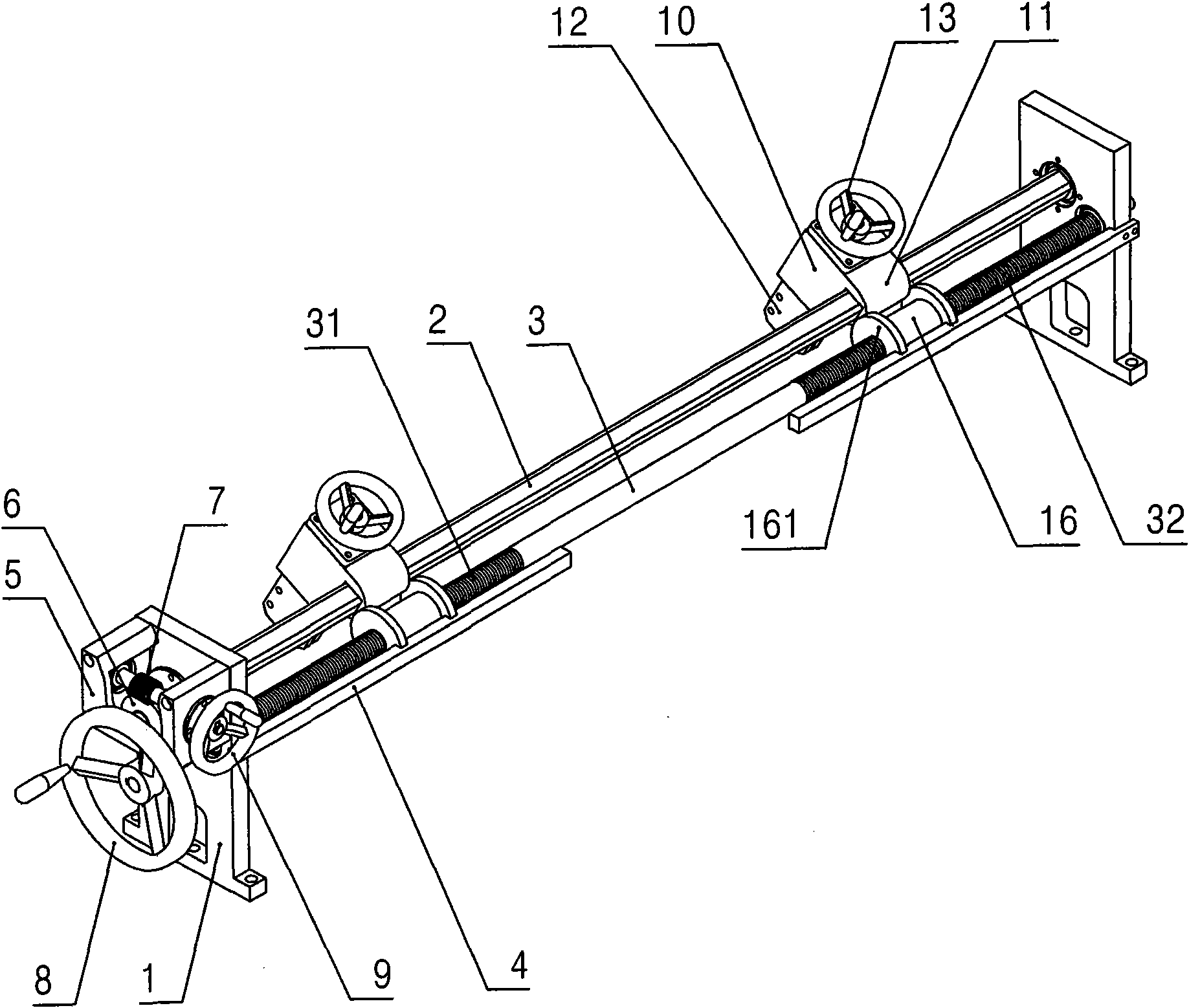
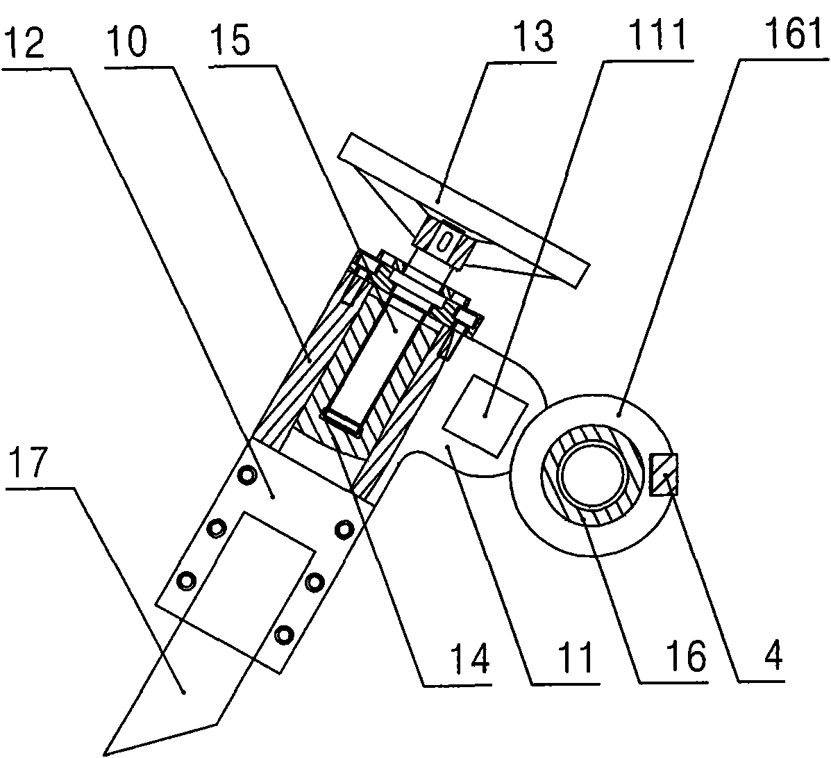
[0018] Such as figure 2 , image 3 and Figure 4 As shown, the width trimming device of the present invention includes: a pair of parallel fixed seats 1 and a pair of knife rests 12 provided with cutting knives 17, and a pair of fixed seats 1 are movably worn with mutually parallel The square shaft 2 and the distance-adjusting screw shaft 3, the left end of the distance-adjusting screw shaft 3 is provided with a distance-adjusting handwheel 8, and the pair of fixed seats 1 are respectively provided with guide rods parallel to the distance-adjusting screw shaft 3 4. The two ends of the distance-adjusting screw shaft 3 are provided with opposite distance-adjusting threads 31 and 32. The tool holder 12 is installed in the tool holder 10, and the lug 11 of the tool holder 10 is provided with a square shaft 2 Matching square support holes, the ...


PUM


Abstract

The invention discloses a breadth edge-cutting device with quite convenient operation and quite easy regulation, which comprises a pair of parallel fixed seats and a pair of knife seats with cutting knives, wherein a square supporting shaft and a distance-regulating lead screw shaft which are mutually parallel are movably penetrated between the pair of fixed seats, reverse threads are arranged at both ends of the distance-regulating lead screw shaft, a guide rod parallel to the distance-regulating lead screw shaft is also arranged on each fixed seat, a supporting hole matched with the cross section of the supporting shaft is arranged on the supporting ear of each knife seat, each knife seat is movably penetrated on the supporting shaft through the supporting hole, a distance-regulating thread sleeve is respectively sleeved on the distance-regulating threads at both ends of the distance-regulating lead screw shaft, and the supporting ear of each knife seat is clamped between a pair of limiting edges of the corresponding distance-regulating thread sleeve; and a worm wheel-worm case is arranged on one fixed seat, a worm wheel and a worm which are mutually matched are arranged in the worm wheel-worm case, the worm wheel is connected with the end part at one corresponding side of the supporting shaft, and a cutting-knife fine-adjusting mechanism is arranged between each knife seat and each cutting knife. The invention is mainly used on flow lines for producing sheet materials, coiled materials and the like.

Description

technical field [0001] The invention relates to a width trimming device used on production lines such as sheets and rolls. Background technique [0002] At present, in the production line of sheet material, coil material, etc., usually adopt figure 1 Width cutter unit shown. In actual use, when adjusting the width (adjusting the lateral distance between the cutters), both ends need to be adjusted separately, that is: adjust the cutter mechanism 1 on the left through the distance adjustment hand wheel 3 on the left, and adjust the cutter mechanism 1 on the left through the distance adjustment handwheel 3 on the right. Adjust the distance adjustment handwheel 4 to adjust the cutter mechanism 2 on the right; If the speed or distance is different, the pair of transverse guide rods 7 and 8 will be inclined, and the pair of vertical moving plates 9 and 10 and the corresponding pair of vertical guide rods 11 and 12 will easily get stuck. The operation must be very careful, so tha...

Claims


Application Information

Patent Timeline
Patent Type & Authority Applications(China)
IPC IPC(8): B26D7/26B26D5/10B26D1/01
Inventor 陆新海朱先福
Owner JIANGSU VICTORY MACHINERY
Why Eureka
Try Eureka