Front section for a motor vehicle body

A car body, car technology, applied in the direction of vehicle components, substructure, vehicle safety arrangements, etc.

Inactive Publication Date: 2011-01-12
GM GLOBAL TECH OPERATIONS LLC
View PDF3 Cites 10 Cited by
  • Summary
  • Abstract
  • Description
  • Claims
  • Application Information

AI Technical Summary

Problems solved by technology

The obturating element thus stiffens the front, which increases the potential danger in the event of a collision with a pedestrian

Method used


Image

  • Front section for a motor vehicle body
  • Front section for a motor vehicle body
  • Front section for a motor vehicle body

Examples


Embodiment Construction

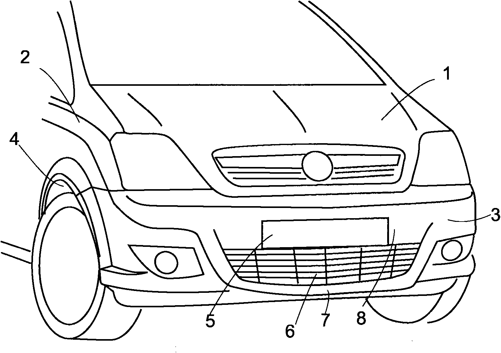
[0021] figure 1 Shown is the front of a car to which the invention can be applied. The part visible at the front basically consists of a front bonnet or bonnet 1, fenders 2 and a plastic molded, soft, shell-like bumper 3 which roughly forms the lower part of the front of the vehicle. Half up to and including the front part of the wheel housing 4. An air intake 6 for cooling air and combustion air is left on the bumper 3 below the number plate area 5 . The lower transverse spacer 7 below the air intake opening 6 forms the region of the bumper 3 and the entire front of the vehicle that protrudes furthest forward. In contrast, the upper transverse positioning element 8 supporting the number plate area 5 is set back slightly.

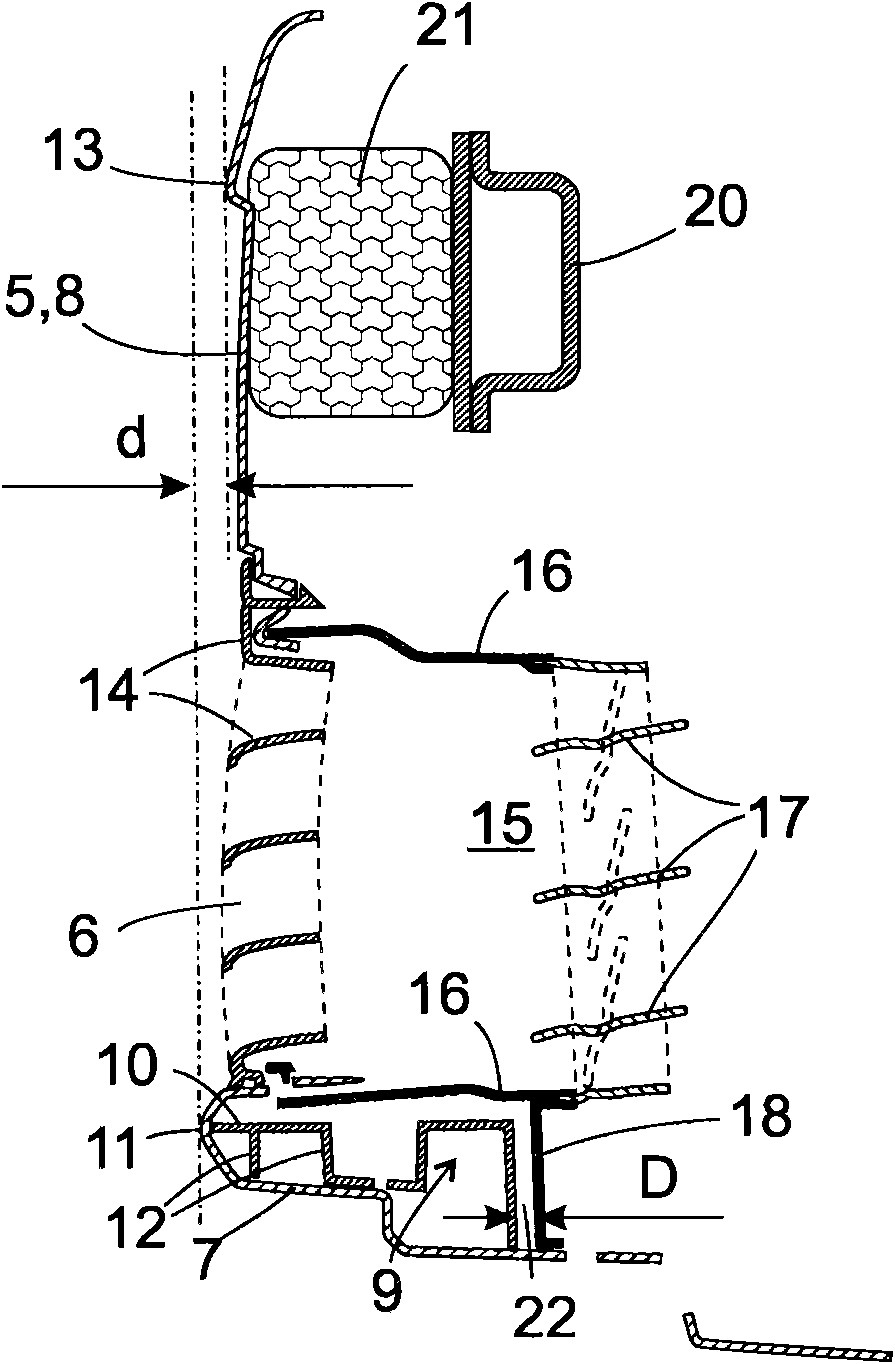
[0022] figure 2 A vertical sectional view of the bumper 3 and its peripheral parts in the longitudinal direction of the vehicle is shown. The lower transverse positioning element 7 is reinforced by a lower bumper bracket 9 injection-molded from plasti...


PUM


Abstract

A front section of a motor vehicle body comprises a bumper (3) and a bumper bracket (9) which are designed to retreat during a collision while absorbing energy and momentum, an air passage (6) and a sealing element (15) situated behind the bumper for modulating the throughput of the fresh air passage and capable of being dragged along by the retreating bumper (3) or bumper bracket (9), and a gap (22)arranged upstream from the sealing element (15) and allowing the bumper (3) and bumper bracket (9) to retreat without simultaneously taking the sealing element (15) with it.

Description

technical field [0001] The invention relates to the front of a motor vehicle body and in particular to the design of such a front with a bumper, a bumper carrier, a fresh air channel and a closure element arranged behind the bumper. Background technique [0002] Generally speaking, the more compact the motor vehicle is and the denser the arrangement of solid parts in the front of the body that deforms in the event of a crash and behind it in the engine compartment that may be relevant for the deformation, the greater this risk. [0003] Recently, it has become more and more common to arrange a controllable closing element, also called a flap, on the fresh air duct in the front of the body, through which the engine is supplied with cooling air and / or combustion air, which Ability to adjust the flow of fresh air channels. For example, by keeping the flow rate low when the engine temperature is low, the engine can reach a stable operating temperature more quickly. As a result...

Claims


Application Information

Patent Timeline
Patent Type & Authority Applications(China)
IPC IPC(8): B60R19/52B60R19/38
CPCB60R2019/1886B60R19/52B60R2019/527B60K11/085B60R2019/186B60R19/34B60R19/18B62D21/152B60R19/12Y02T10/88
Inventor 沃尔克·伯恩特罗尔夫·尤尔特
Owner GM GLOBAL TECH OPERATIONS LLC
Why Eureka
Try Eureka