Improved structure of transferring belt conveyer

A belt conveyor and improved structure technology, applied in the direction of conveyors, conveyor objects, transportation and packaging, etc., can solve the problems of being unable to be sent away, and achieve the effects of reduced floor space, large operating space, and compact design structure

Inactive Publication Date: 2011-01-12
健伦精密机械(中国)有限公司
View PDF7 Cites 5 Cited by
  • Summary
  • Abstract
  • Description
  • Claims
  • Application Information

AI Technical Summary

Problems solved by technology

[0003] In order to overcome the above-mentioned defects, the present invention provides an improved structure of the pick-up b

Method used


Image

  • Improved structure of transferring belt conveyer
  • Improved structure of transferring belt conveyer

Examples


Example Embodiment

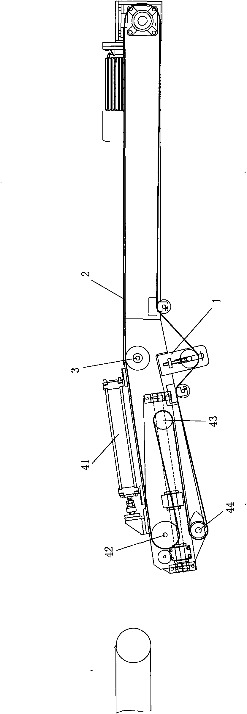
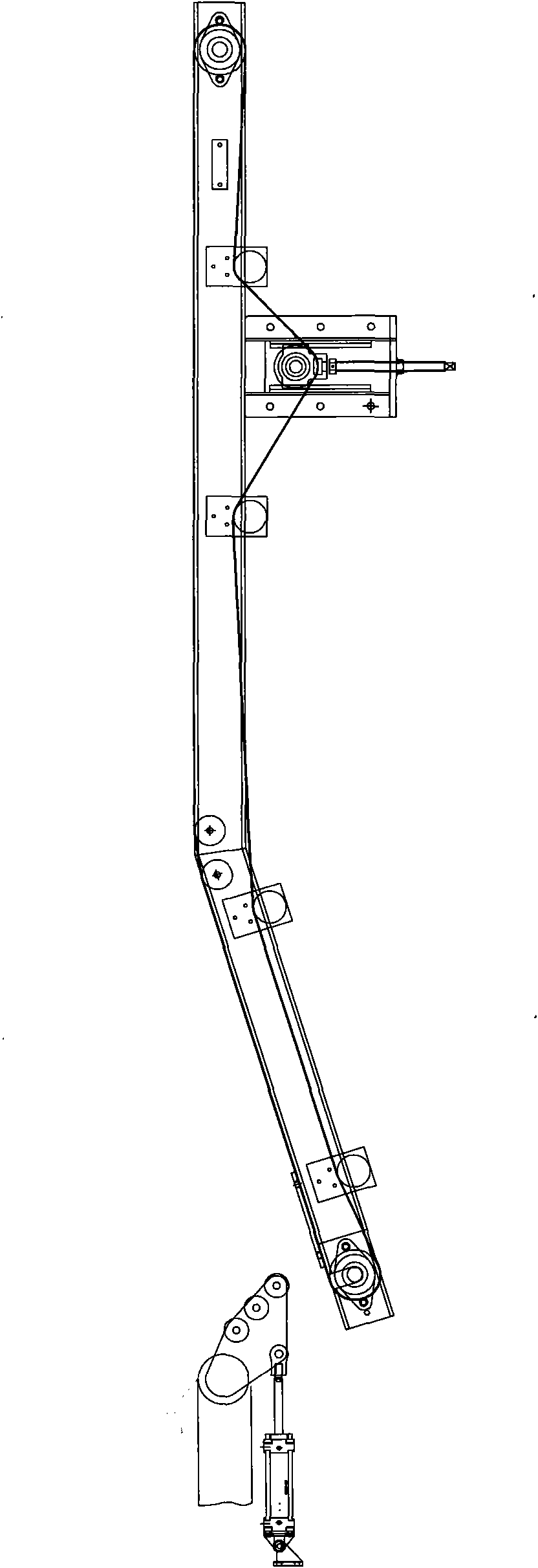
[0010] Embodiment: An improved structure of a shuttle belt conveyor, which includes a fixed frame 1, a conveyor belt 2 and a roller 3. The conveyor belt 2 is wound on the fixed frame 1, and the conveyor belt 2 is arranged on the frame The fixed frame 1 has a telescopic end 4 at one end. The telescopic end 4 includes a driving device 41, an active roller 42, a number of passive rollers 43, and a positioning roller 44. The driving device 41 is fixed to the machine On the frame and connected to drive the active roller to telescopically move towards one side of the frame, the passive roller 43 is fixed at the telescopic end of the frame and can telescopically move in the driving direction of the active roller, and the positioning roller 44 is fixed to the telescopic end of the frame. The conveyor belt 2 is simultaneously wound on the active roller 42, a number of passive rollers 43 and the positioning roller 44 for connection transmission. The driving device 41 drives the active rol...


PUM


Abstract

The invention discloses an improved structure of a transferring belt conveyer, comprising a fixed rack, a conveyer belt and a roller, wherein the rack is provided with a flexible end to replace the original swinging receiving roller mechanism so as to effectively avoid the defect that the material can not be sent away because of falling into a gap between the swinging receiving rollers; and meanwhile, the design construction is more compact, has larger operation space and reduces the floor area while keeping the whole occupation space constant.

Description

technical field [0001] The invention relates to a conveyor, in particular to an improved structure of a pick-up belt conveyor. Background technique [0002] The pick-up belt conveyor is a conveyor specially designed for continuous and alternate pick-up of materials under at least two working conditions. It is an improved version of the ordinary belt conveyor. The original method is to use a combination of a conveyor and a swing take-up roller mechanism, such as figure 1 Said: When the swing receiving roller mechanism swings up and is in the receiving position, the material can slide from the roller to the receiving belt conveyor, and then be sent away; the disadvantage is that when the material is relatively soft, the material is easy to fall into the In the gap between the swing receiving rollers, this is not allowed on the continuous conveying production line, otherwise it will affect the production efficiency or product quality; if the material does not need to be sent t...

Claims


Application Information

Patent Timeline
IPC IPC(8): B65G47/52B65G15/26
Inventor 蒋昌贤
Owner 健伦精密机械(中国)有限公司
Why Eureka
Try Eureka