Temperature sensor structure of microwave oven

A technology of temperature sensor and microwave oven, applied in the field of microwave oven, can solve the problem that the positioning accuracy of the sensor probe cannot be accurately guaranteed, increase the overall production cost of the microwave oven, affect the accurate and normal operation of the microwave oven, etc. offset effect

Inactive Publication Date: 2014-06-04
LG ELECTRONICS (TIANJIN) APPLIANCES CO LTD
View PDF5 Cites 0 Cited by
  • Summary
  • Abstract
  • Description
  • Claims
  • Application Information

AI Technical Summary

Problems solved by technology

[0009] In the prior art, the mutual fixing between the sensor probe and the sensor housing needs to be realized by using additional accessories such as screws, thus increasing the overall production cost of the microwave oven, and the positioning accuracy of the sensor probe cannot be accurately guaranteed when it is fixed. Therefore, it will cause the sensor probe to deviate when collecting data, which will affect the accurate and normal operation of the microwave oven.

Method used


Image

  • Temperature sensor structure of microwave oven
  • Temperature sensor structure of microwave oven
  • Temperature sensor structure of microwave oven

Examples


Embodiment Construction

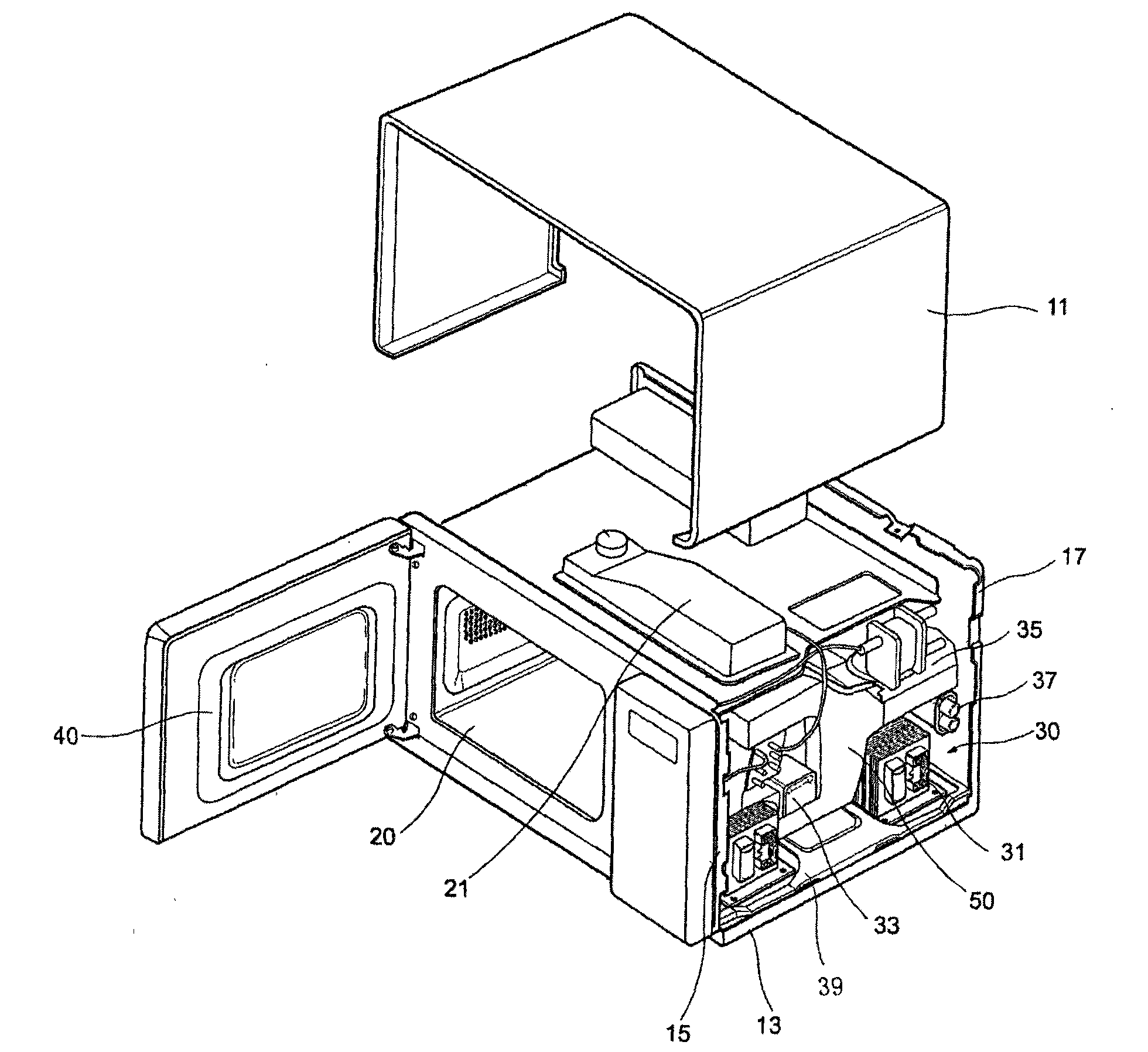
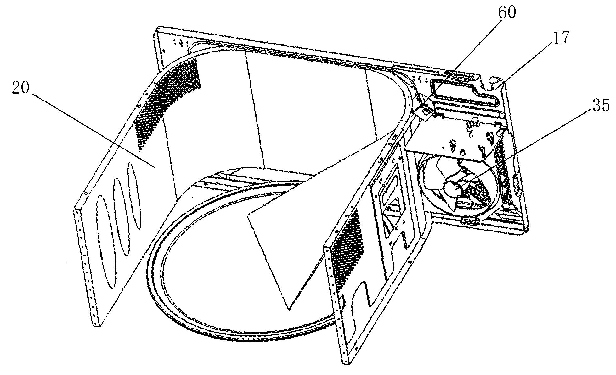
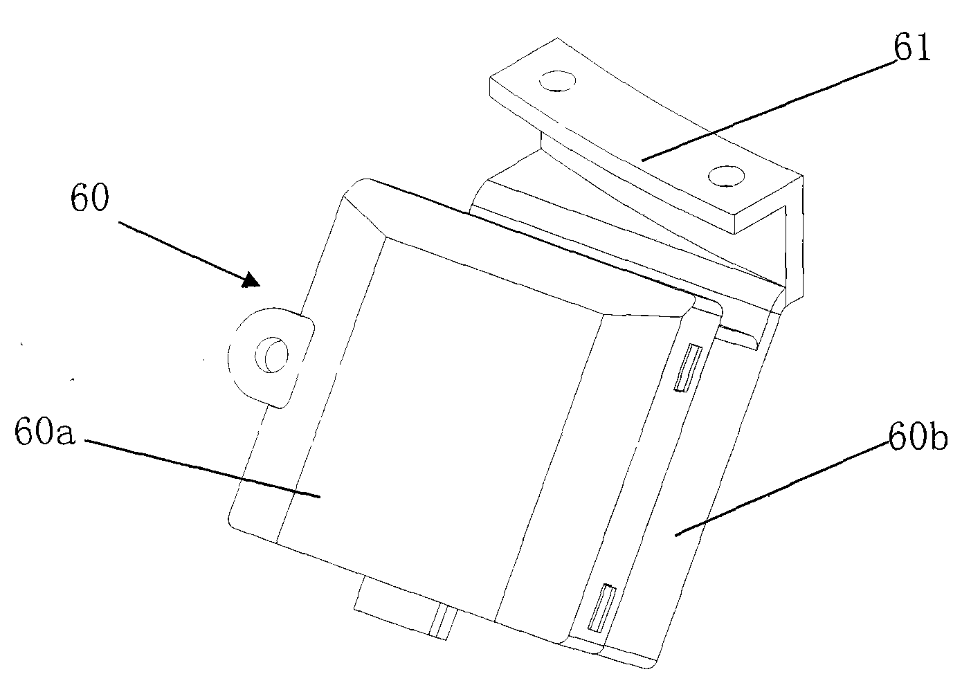
[0028] The present invention is described in detail below with reference to accompanying drawing and embodiment:

[0029] Figure 4 is a schematic diagram of the temperature sensor structure of the microwave oven of the present invention; Figure 5 It is a structural schematic diagram of the lower cover of the housing in the temperature sensor structure of the microwave oven of the present invention; Image 6 It is a structural schematic diagram of the shell upper cover in the temperature sensor structure of the microwave oven of the present invention.

[0030] like Figure 4 to Figure 6 As shown, the temperature sensor structure of the microwave oven of the present invention includes: a sensor probe, which is arranged outside the oven cavity of the microwave oven, and receives the infrared signal sent by the food in the oven cavity through the observation hole formed on the oven cavity and measures the temperature of the food. The temperature signal is converted into an el...


PUM


Abstract

The invention relates to a temperature sensor structure of a microwave oven, comprising sensor probes, sensor shells and probe holes, wherein the inside of the lower cover of the shell is provided with a plurality of supporting poles for supporting the sensor probes; the top ends of partial supporting poles are provided with protuberant positioning pins; the positioning pins are asymmetrically distributed; a fixing plate on the sensor probe is provided with positioning holes the quantity and the positions of which correspond to the quantity and positions of the positioning pins; when the sensor probe is loaded into the sensor shell, the positioning pins are mutually and correspondingly matched with the positioning holes; the bottom of the interior space of the lower cover of the shell is provided with a prominent positioning plate; and the upper cover of the shell is provided with oppression columns. The fixing positions of the sensor probes of the invention are more precise so that the positions of the probes mutually and correctly correspond to the probe holes at the bottom of the lower cover of the shell, thereby avoiding deviation, simplifying production and installation procedures, further saving cost and improving production efficacy.

Description

technical field [0001] The invention belongs to the technical field of microwave ovens, and in particular relates to a microwave oven in which various positioning components such as positioning pins, positioning plates, and pressing columns are arranged inside the sensor shell, so that the sensor probe can be accurately fixed in the sensor shell and the production cost can be saved. Temperature sensor structure. Background technique [0002] A microwave oven is a device in which a magnetron generates microwaves after the power is turned on, and irradiates these microwaves on food and other heated objects to cook food. Such microwave ovens are classified into domestic microwave ovens equipped with small magnetrons and commercial microwave ovens equipped with large or multiple magnetrons. Microwave ovens can also be divided into household microwave ovens that generally use a glass turntable that rotates food, and commercial microwave ovens that mainly use a diffuser plate tha...

Claims


Application Information

Patent Timeline
Patent Type & Authority Patents(China)
IPC IPC(8): F24C7/08F24C7/02G01J5/00
Inventor 彭飞张国君袁准齐静明方亚林
Owner LG ELECTRONICS (TIANJIN) APPLIANCES CO LTD
Why Eureka
Try Eureka