Supercharge Your Innovation With Domain-Expert AI Agents!

Curved surface detector

A detector and curved surface technology, applied in the field of curved surface detectors, can solve problems such as poor imaging performance, easy overweight, complex structure, etc., and achieve the effects of total weight reduction, cost reduction, and simple structure

Inactive Publication Date: 2011-01-12
XI'AN INST OF OPTICS & FINE MECHANICS - CHINESE ACAD OF SCI
View PDF0 Cites 1 Cited by
  • Summary
  • Abstract
  • Description
  • Claims
  • Application Information

AI Technical Summary

Problems solved by technology

[0005] The purpose of the present invention is to provide a curved surface detector to overcome the technical problems of complex structure, easy overweight and poor imaging performance in the existing optical system design

Method used


Image

  • Curved surface detector
  • Curved surface detector
  • Curved surface detector

Examples


Embodiment Construction

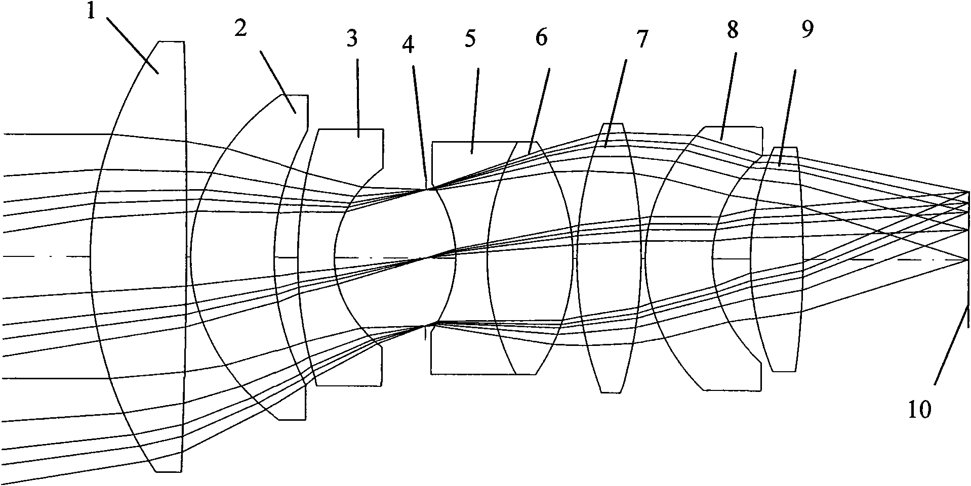
[0021] see figure 1 , the optical system is mainly composed of eight lenses from left to right to form a transmissive optical system, and finally the outgoing rays of different field of view rays (that is, the angles of incident rays) are all imaged on the flat detector to form an image plane. The specific optical path is: the light propagates from left to right in the figure, the light is first incident on the incident surface of the lens 1 in the figure, then passes through the lenses 2 and 3 respectively according to the law of refraction, and then passes through the light hole 4 (this aperture Limit the imaging beam of the entire optical system, that is, the light outside the aperture will be blocked by this aperture and will not be able to image on the image plane), the light from the light hole 4 passes through a doublet lens composed of 5 and 6, and then After passing through the lenses 7 , 8 , and 9 in sequence, the light rays of different fields of view will intersect...


PUM


Abstract

The invention relates to a curved surface detector, and the detector is shaped like a curved surface. As the detector is shaped like the curved surface, the detector can correct excessive field curvature and astigmatism in comparison with a plane detector, thereby leading other lenses to share other monochromatic aberrations in a greater manner, further improving the imaging quality of an optical system, appropriately improving the structure, simplifying the structure, reducing the total weight, reducing the cost and facilitating the carrying.

Description

technical field [0001] The invention belongs to optical imaging technology or optical detection technology, in particular to a curved surface detector. Background technique [0002] In the design process of the existing optical system, the indicators required by the system are achieved by combining different lenses; no matter how complicated the optical system is, it can be basically added a certain number of lenses at the appropriate position and then optimized by software, and finally achieve The indicators we need; but adding lenses will bring two problems: 1. Increased cost: this is what all optical design workers are reluctant to see; 2. For some lenses with special requirements, if more The lens will cause the weight and size of the lens to exceed the standard, but for some load devices such as star sensors, the weight and size exceeding the standard are unacceptable. In such a case, the number of lenses can only be reduced and redesigned, so it is very likely that th...

Claims


Application Information

Patent Timeline
IPC IPC(8): G01D21/00G01D11/24
Inventor 张彭舜达争尚白秋菊
Owner XI'AN INST OF OPTICS & FINE MECHANICS - CHINESE ACAD OF SCI
Features
  • R&D
  • Intellectual Property
  • Life Sciences
  • Materials
  • Tech Scout
  • Unparalleled Data Quality
  • Higher Quality Content
  • 60% Fewer Hallucinations
Learn More