
A method and system for realizing synchronous binding of security keys

A technology for security keys and keys, applied in the field of security authentication, can solve the problems of inability to ensure the data security of RN and network communication, and inability to realize user authentication and device binding of the RN, and achieve the effect of protecting security.

Active Publication Date: 2015-12-16
ZTE CORP
View PDF3 Cites 0 Cited by
  • Summary
  • Abstract
  • Description
  • Claims
  • Application Information

AI Technical Summary

Problems solved by technology

Therefore, the existing legality authentication for RN cannot guarantee that a legal USIM card is inserted into a legal RN device, that is, the user authentication of RN and the binding of devices cannot be realized, so that the communication data security between RN and the network side cannot be guaranteed

Method used


Image

  • A method and system for realizing synchronous binding of security keys
  • A method and system for realizing synchronous binding of security keys
  • A method and system for realizing synchronous binding of security keys

Examples


Embodiment Construction

[0055] Figure 4 The flow chart of the method for realizing the synchronous binding of security keys in the present invention includes the following steps:

[0056] Step 400: MME notifies RN to perform security key binding.

[0057] In this step, the MME may send a NAS message to the RN to notify the RN to bind the security key. Among them, the NAS message can reuse the existing NAS message, such as the NAS security mode command (NASSMC, NASSecurityModeCommand) message, or the user authentication request (UserAuthenticationRequest) message, etc.; the NAS message can also be a new message, such as a key binding request information.

[0058] If the RN and the network side agree that after the NAS message used to notify the RN to bind the security key, the security key binding process must be performed, then the NAS message in this step does not need to carry any information, it is a notification Instruction, that is, the RN and the network use an implicit method to bind the s...


PUM


Abstract

The invention discloses a method and system for synchronous binding of security keys, including that after the RN passes the user authentication, the MME notifies the RN to bind the security key; Key binding processing, obtain the security key bound with the device, and respond to MME. Through the method of the present invention, the security key bound to the device obtained through the security key binding process, or other keys derived from the security key bound to the device, protects the communication between the RN and the network side Data Security. Moreover, through the security key bound to the device, RN user authentication and device binding are realized, and it is guaranteed that the RN communicating with the network side at this time must be a legal RN with a legal USIM card. In this way, an illegal attacker Communication data cannot be deciphered.

Description

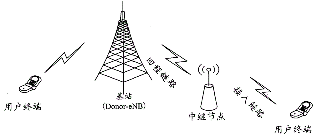
technical field [0001] The invention relates to a security authentication technology in an LTE network, in particular to a method and a system for realizing synchronous binding of a security key. Background technique [0002] figure 1 It is a schematic diagram of the composition structure of a long-term evolution (LTE, LongTermEvolution) network, such as figure 1 As shown, the LTE network is composed of an Evolved Universal Terrestrial Radio Access Network (E-UTRAN, Evolved Universal Terrestrial Radio Access Network) and an Evolved Packet Switching Center (EPC, Evolved Packet Core), and the network is flat. EUTRAN is connected with EPC through S1 interface. [0003] Among them, EUTRAN is composed of multiple interconnected evolved base stations (eNB, EvolvedNodeB), and each eNB is connected through the X2 interface; EPC is composed of a mobility management entity (MME, MobilityManagementEntity) and a serving gateway entity (S-GW, ServingGateway) . In addition, there is a...

Claims


Application Information

Patent Timeline
Patent Type & Authority Patents(China)
IPC IPC(8): H04W12/04H04W12/06H04W12/041
CPCH04W12/041H04W12/122
Inventor 和峰冯成燕
Owner ZTE CORP
Learn More