
Method and system for reporting scheduling information

A technology for dispatching information and logical channels, applied in wireless communication, advanced technology, network traffic/resource management, etc., can solve problems such as high interference, inability to use more terminal power margin, and reduced effective rate of terminal data, to achieve Realize the effect of resource scheduling

Active Publication Date: 2011-01-12
浙江杭海新城控股集团有限公司
View PDF3 Cites 0 Cited by
  • Summary
  • Abstract
  • Description
  • Claims
  • Application Information

AI Technical Summary

Problems solved by technology

[0012] It can be seen that, using the scheduling information obtained according to the existing rules, although there is information in the terminal power net space domain, Node B still cannot accurately know the specific power headroom conditions corresponding to each carrier, resulting in the fact that Node B cannot know more The terminal power headroom is used inappropriately for higher rate and higher power data transmission, that is, the rate at which the terminal sends data cannot be increased; or, in fact, Node B may use the terminal power headroom incorrectly for higher rate, higher power data transmission, that is, the rate at which the terminal sends data is incorrectly increased
In either case, Node B cannot make full use of system resources and terminal power, so that it cannot provide optimal scheduling that matches the current network performance and terminal interference conditions. In extreme cases, it will lead to unreasonable power increases and interference If the value is too high, the user capacity will be reduced, the effective rate of data sent by the terminal will be reduced, and the catastrophic consequences will be dropped.

Method used


Image

  • Method and system for reporting scheduling information
  • Method and system for reporting scheduling information
  • Method and system for reporting scheduling information

Examples


example 1

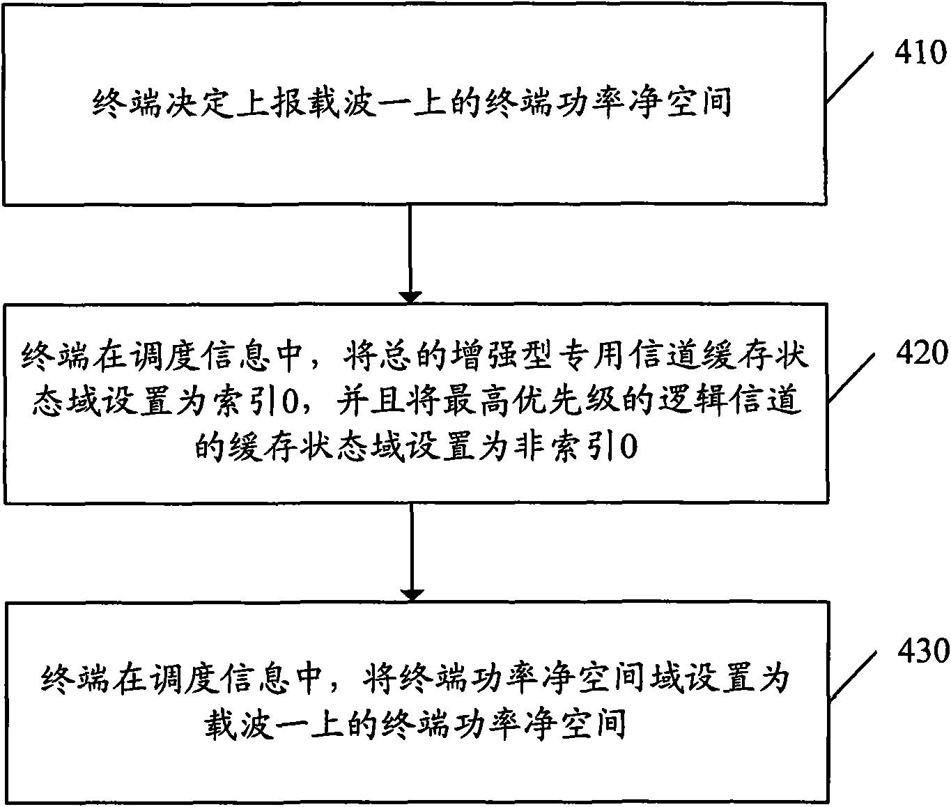
[0081] Example 1: The scheduling information reported by the terminal side includes the terminal power headroom of the carrier 1. Such as figure 2 As shown, the specific process of reporting in this instance includes the following steps:

[0082] Step 410, the terminal decides to report the terminal power headroom on carrier one.

[0083] Step 420: In the scheduling information, the terminal sets the buffer status field of the general enhanced dedicated channel as index 0, and sets the buffer status field of the highest priority logical channel as non-index 0.

[0084] Here, the value of non-index 0 refers to any value of non-index 0 among all the values ​​of the buffer state field of the highest priority logical channel with a length of 4 bits.

[0085] Step 430, the terminal sets the terminal power headroom domain as the terminal power headroom on carrier one in the scheduling information.

[0086] Here, the terminal power net space field indicates: the ratio of the maxi...

example 2

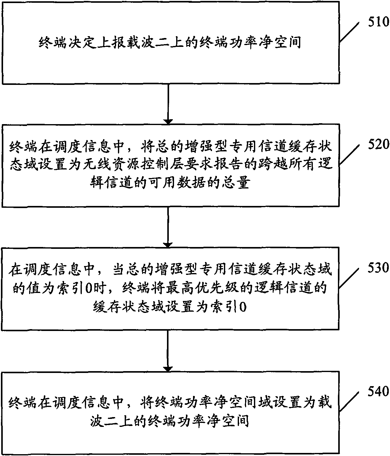
[0087] Example 2: The scheduling information reported by the terminal side includes the terminal power headroom of the carrier 2. Such as image 3 As shown, the specific process of reporting in this instance includes the following steps:

[0088] Step 510, the terminal decides to report the terminal power headroom on the second carrier.

[0089] Step 520: In the scheduling information, the terminal sets the total enhanced dedicated channel buffer state field as the total amount of available data across all logical channels that the radio resource control layer requires to report.

[0090] Step 530: In the scheduling information, when the value of the total enhanced dedicated channel buffer state field is index 0, the terminal sets the buffer state field of the highest priority logical channel as index 0.

[0091] Here, step 530 may also be: when the value of the total enhanced dedicated channel cache state field is not index 0, the terminal sets the cache state field of the ...

example 3

[0094] Example 3: The situation where the Node B side parses the reported scheduling information. Such as Figure 4 As shown, the specific process of parsing in this example includes the following steps:

[0095] Step 610, when the total enhanced dedicated channel cache status field in the scheduling information indicates index 0, and the cache status field of the highest priority logical channel indicates non-index 0, then go to step 620; otherwise, go to Step 630 is executed.

[0096] Here, the value of non-index 0 refers to any value of non-index 0 among all the values ​​of the buffer state field of the highest priority logical channel with a length of 4 bits.

[0097] Step 620, Node B considers that the terminal power headroom domain refers to the terminal power headroom on carrier one.

[0098] Here, the terminal power net space field indicates: the ratio of the maximum transmit power of the terminal to the code power of the corresponding dedicated physical control cha...


PUM


Abstract

The invention discloses a method for reporting scheduling information. The method comprises the following steps: a terminal reports the scheduling information to the base station, wherein in the indication mode of combining domain combination values in scheduling information, the scheduling information indicates that in the scheduling information, the current terminal power clear space is the terminal power clear space corresponding to one of the two carriers. The invention also discloses a system for reporting scheduling information. A reporting unit in the system at the terminal side is used for reporting the scheduling information to the base station, wherein in the indication mode of combining domain combination values in scheduling information, the scheduling information indicates that in the scheduling information, the current terminal power clear space is the terminal power clear space corresponding to one of the two carriers. The method and system can be used for reporting scheduling information; and the scheduling information can clearly indicate that the terminal power clear space domain in the scheduling information aims at the terminal power clear space of one of the two carriers, thereby facilitating the pertinent analysis of the base station and scheduling the resources in a better way.

Description

technical field [0001] The present invention relates to a scheduling information reporting technology in a wireless communication system, in particular to a method and system for reporting scheduling information when data transmission is performed on dual carriers using high-speed packet access technology. Background technique [0002] In the existing system, the scheduling information is the reference information for scheduling by the most core Node B. Here, the Node B is the Node B of the base station. The scheduling information method in the existing system is as follows: [0003] The scheduling information is located at the end of the protocol data unit of the MAC entity handling the enhanced dedicated channel. The scheduling information is used to give the Node B a better perspective to observe the total amount of system resources required by the terminal and the total amount of system resources actually used or available by the terminal. Scheduling information is se...

Claims


Application Information

Patent Timeline
IPC IPC(8): H04W28/14H04W28/24H04W72/12
CPCY02D30/70
Inventor 程翔贺美芳张瑜
Owner 浙江杭海新城控股集团有限公司
Learn More