Constant temperature parameter variable electric heating system

A technology of electric heating and power supply system, which is applied in the direction of electric furnace heating, ohmic resistance heating, electric heating devices, etc., and can solve problems such as inability to adapt to complex and changeable, fixed constant temperature parameters, and inability to adapt to different needs

Inactive Publication Date: 2014-03-26
苏欣捷
View PDF6 Cites 2 Cited by
  • Summary
  • Abstract
  • Description
  • Claims
  • Application Information

AI Technical Summary

Problems solved by technology

[0008] The purpose of the present invention is to overcome the deficiencies of the prior art, provide an electric heating system with variable constant temperature parameters, and solve the problem that the

Method used


Image

  • Constant temperature parameter variable electric heating system
  • Constant temperature parameter variable electric heating system
  • Constant temperature parameter variable electric heating system

Examples


Embodiment 1

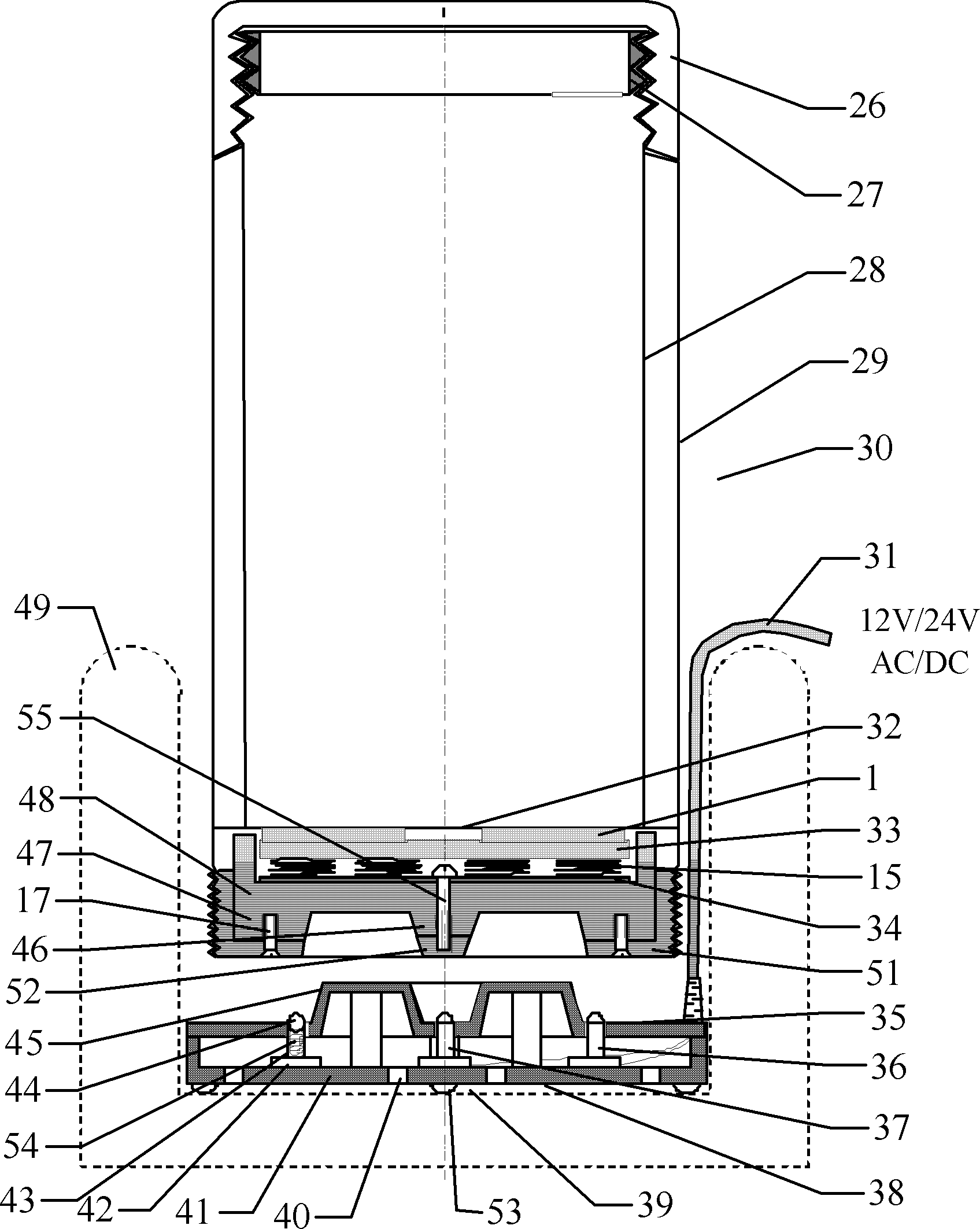
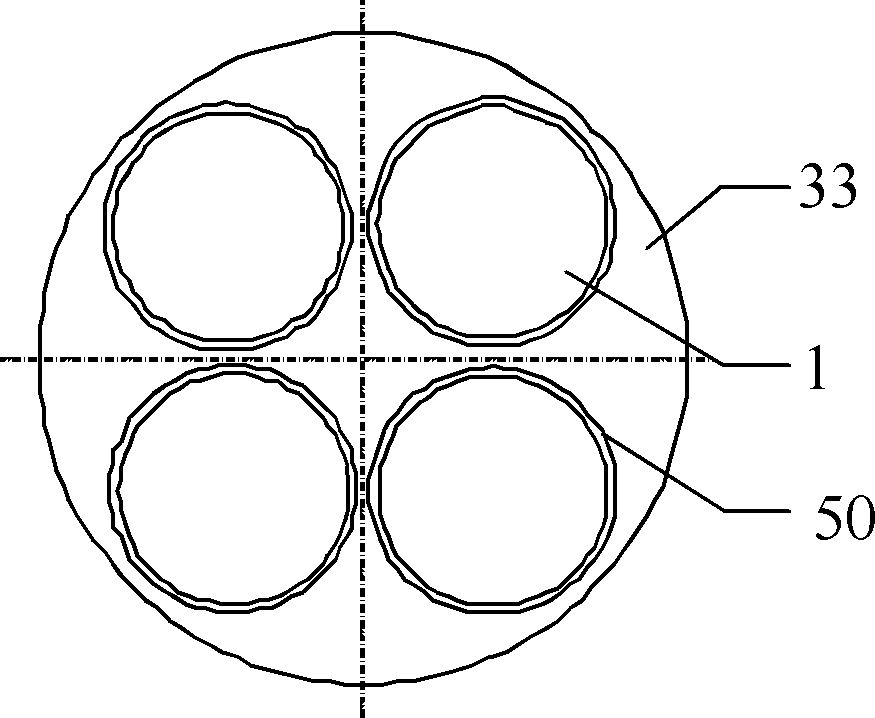
[0097] figure 1 It shows an embodiment of PTC electric constant temperature cup and power supply system. The cup inner bottom part 32 of the PTC electric constant temperature cup 30 adopts a stainless steel plate, and four circular PTC heating elements 1 are arranged in four grooves 50 of the electrode plate 33, see figure 2 . The four circular PTC heating elements 1 have a diameter of 20mm, a thickness of 1.5mm, a surface temperature of 60±5°C, and an operating voltage of 12V. The disc-shaped electrode plate 33 is made of aluminum plate with a thickness of 3mm and a groove depth of 0.7mm. The PTC heating element 1 is pressed on the lower side of the cup inner bottom 32 by the disc-shaped electrode plate 33 and the spring 15 at its lower part. The lower side of the spring 15 is a metal conductive plate 34 and an outer bottom member 48, and the metal conductive plate 34 is made of an aluminum plate with a thickness of 1mm. The outer bottom part 48 adopts plastic injection m...

Embodiment 2

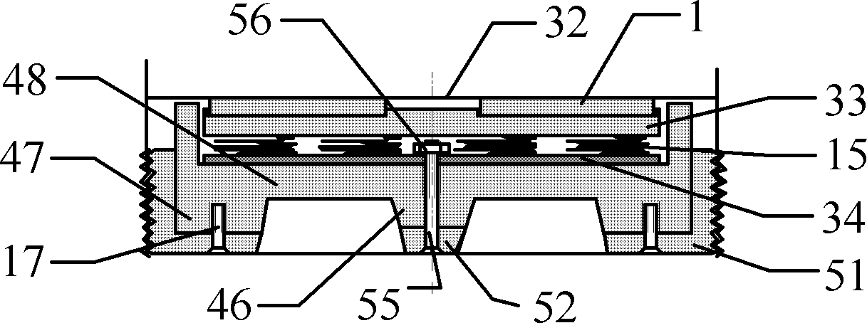
[0099] The difference between this embodiment and Embodiment 1 is that the central electrode pole shoe 52, such as image 3 As shown, the screw 55 passes through the central electrode pole piece 52 with a through hole, and the outer bottom member 48 and the through hole of the metal conductive plate 34 are fixed with the nut 56 on the upper part thereof. The embodiment of the central electrode seat 12 and the central electrode pole shoe 30 is defined as mode B.

Embodiment 3

[0101] Such as Figure 4 As shown, the difference between this embodiment and Embodiment 1 is that the central electrode pole piece 52 is enlarged to completely replace the central electrode seat 46, adopts a circular frustum shell structure, and is installed in a circular groove of the outer bottom member 48, and the screw 55 passes through A through hole at the center of the metal conductive plate 34 and the outer bottom member 48 is fixed with a nut 56 welded in the frustum shell. The central electrode shoe of the circular frustum shell is stamped and formed by stainless steel plate. Spring 15 adopts leaf spring. The embodiment of the central electrode holder 12 and the central electrode shoe 30 is defined as mode C.


PUM


Abstract

An electric heating system whose constant temperature parameter is variable comprises at least one electric heating assembly, a component to be maintained constant temperature(4), a constant temperature controlling apparatus, a power supply system and PTC element or unit that can be replaced or switched; the connections between the electric heating assemblies and the component to be maintained constant temperature are heat conductions, the at least one electric heating assembly and the power supply is connected electrically when the electrical heating system is operating. The invention resolves the following problems that the constant temperature parameter of existing PTC heating system is invariable and the PTC heating system is not available for different needs and complicated conditions.

Description

technical field [0001] The invention relates to an electric heating system, in particular to an electric heating system with variable constant temperature parameters, which has a temperature-controlled heating device whose heating material is non-metal. Background technique [0002] The constant temperature control method of traditional electric heating systems usually uses thermal sensors to detect temperature changes, and then feeds them back to the heating operation of the heating element to compensate for the temperature changes that occur. Its disadvantage is that it is more complicated and expensive, but its reliability is not high. In recent years, the development and application of positive temperature coefficient (Positive Temperature Coefficient, PTC) thermal element heating technology has made great progress, providing a simple, affordable and highly reliable heating and temperature control integration for the field of temperature control. Specialized heating and...

Claims


Application Information

Patent Timeline
IPC IPC(8): H05B3/22A47J27/21H05B3/26F27D11/02
CPCA47J27/2105H05B3/12H05B2203/02A47J36/2472
Inventor 苏欣捷
Owner 苏欣捷
Why Eureka
Try Eureka