

Energy-saving fender for motor vehicle
A technology of motor vehicles and wings, applied in the direction of body, body stability, vehicle parts, etc., to achieve the effect of reducing pressure, simple structure, and ensuring control performance
Inactive Publication Date: 2011-01-19
石金成
View PDF1 Cites 19 Cited by
- Summary
- Abstract
- Description
- Claims
- Application Information
AI Technical Summary
Problems solved by technology
The purpose of the present invention is to provide a motor vehicle energy-saving wing plate, which solves the technical problems of saving energy consumption and reducing emissions when the motor vehicle is running at low speed
Method used
View moreImage
Smart ImageViewing Examples

Examples
Embodiment Construction
Login to View More PUM
 Abstract
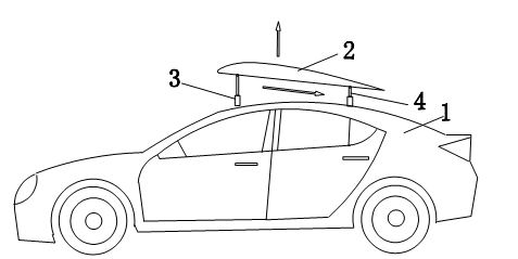
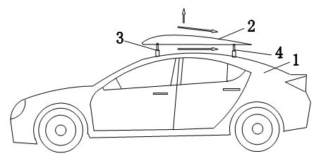
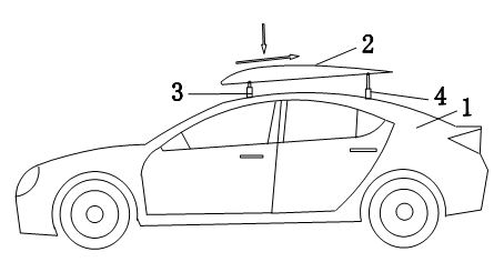
An energy-saving fender for a motor vehicle is characterized in that a fixed fender (2) is arranged above the top surface of a body (1) of a motor vehicle, wherein space exists between the top surface of the vehicle and the fender; and the fender and the horizontal plane form an elevation angle of 0-20 degrees. The fender has the following beneficial effects: the fender changes the aerodynamic configuration of the motor vehicle, generates extra lift force when the motor vehicle travels at low speed so as to reduce the pressure of the wheels of the motor vehicle on the ground, ensures low frictional resistance between the wheels and the pavement, so that the motor vehicle consumes less energy during travelling, and can ensure the control performance of the vehicle and travelling safety.
Description
technical field [0001] The invention relates to a motor vehicle auxiliary flap device, in particular to a motor vehicle energy-saving flap applied to various motor vehicles such as cars, vans, passenger cars and trucks. Background technique [0002] At present, some cars are equipped with a spoiler, that is, the spoiler of the car, which refers to the additional plate installed above the rear of the car. The role of the spoiler is mainly to reduce the lift at the rear of the vehicle. If the lift at the rear of the car is greater than that at the front, it will easily lead to excessive steering, reduced rear wheel grip, and poor high-speed stability. Utilize the inclination of the spoiler to make the wind directly generate downward pressure, such as the spoiler at the rear of an F1 racing car is generally inclined at 15°, and the pressure can reach more than 1000 kg when driving at high speed. Some station wagons have a spoiler installed on the rear edge of the top cove...
Claims
Login to View More Application Information
Patent Timeline
 IPC IPC(8): B62D37/02
Inventor石金成石超田园田瑞民
Owner石金成