Clamp unhooking device

A pliers-type and pliers-piece technology, which is applied in the field of pliers-type hook uncoupling devices and hoisting traction devices, can solve problems such as low safety performance, inaccurate landing position, and violent swing of the decoupling device, and achieve the position of the decoupling landing point Precise, simple and compact structure, safe and reliable work

Active Publication Date: 2011-01-19
CEEC JIANGSU ELECTRIC POWER DESIGN INST
View PDF4 Cites 2 Cited by
  • Summary
  • Abstract
  • Description
  • Claims
  • Application Information

AI Technical Summary

Problems solved by technology

The single-hook flip-type decoupling device will generate lateral force when decoupling, causing the decoupling device to swing violently after decoupling. After the heavy object is decoupled, it is easy to cause space drift, the landing point position is inaccurate, and the neutrality is relatively poor. It is mainly used for heavy objects. Occasions where the position of the landing point is not high
Chinese patent document CN92223321.7 discloses an automatic uncoupling device, which belongs to the single-hook flip type uncoupling device, which improves the sensitivity of decoupling and overcomes the space drift caused by the decoupling of heavy objects, but the safety performance is not high
Chinese patent document CN87209663 discloses a load and unloading uncoupling device, which belongs to the pincer type uncoupling device. The technical scheme is simple in structure, and it is indeed better when the requirements for the unloading position are not high, but it is inconvenient to operate and the safety performance is not good. High, it is not suitable for applications such as test detection and other fields that require high neutrality
In short, the current decoupler still has the problems of inconvenient operation, poor safety, and inaccurate unloading position.

Method used


Image

  • Clamp unhooking device
  • Clamp unhooking device
  • Clamp unhooking device

Examples


Embodiment 1

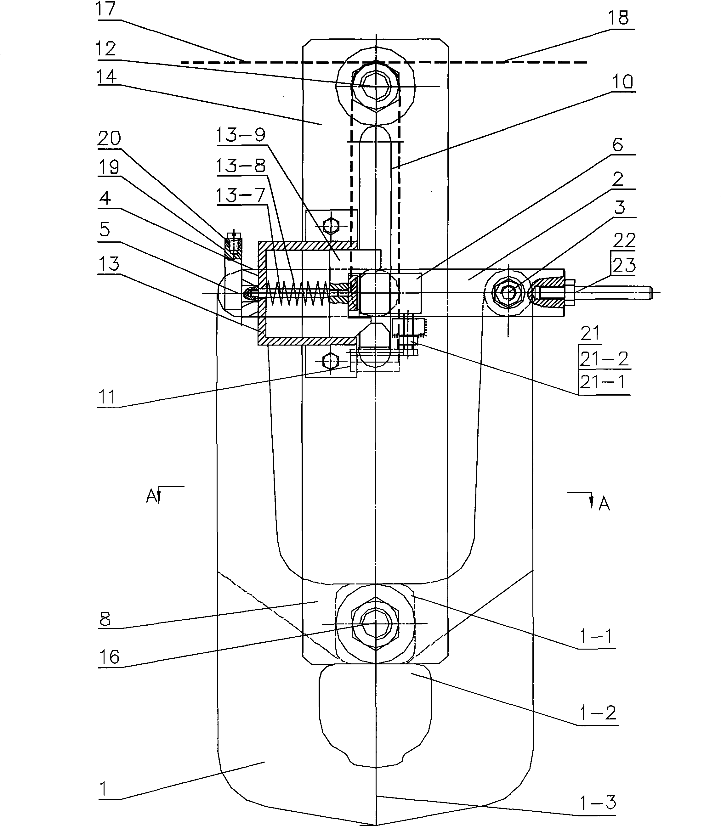
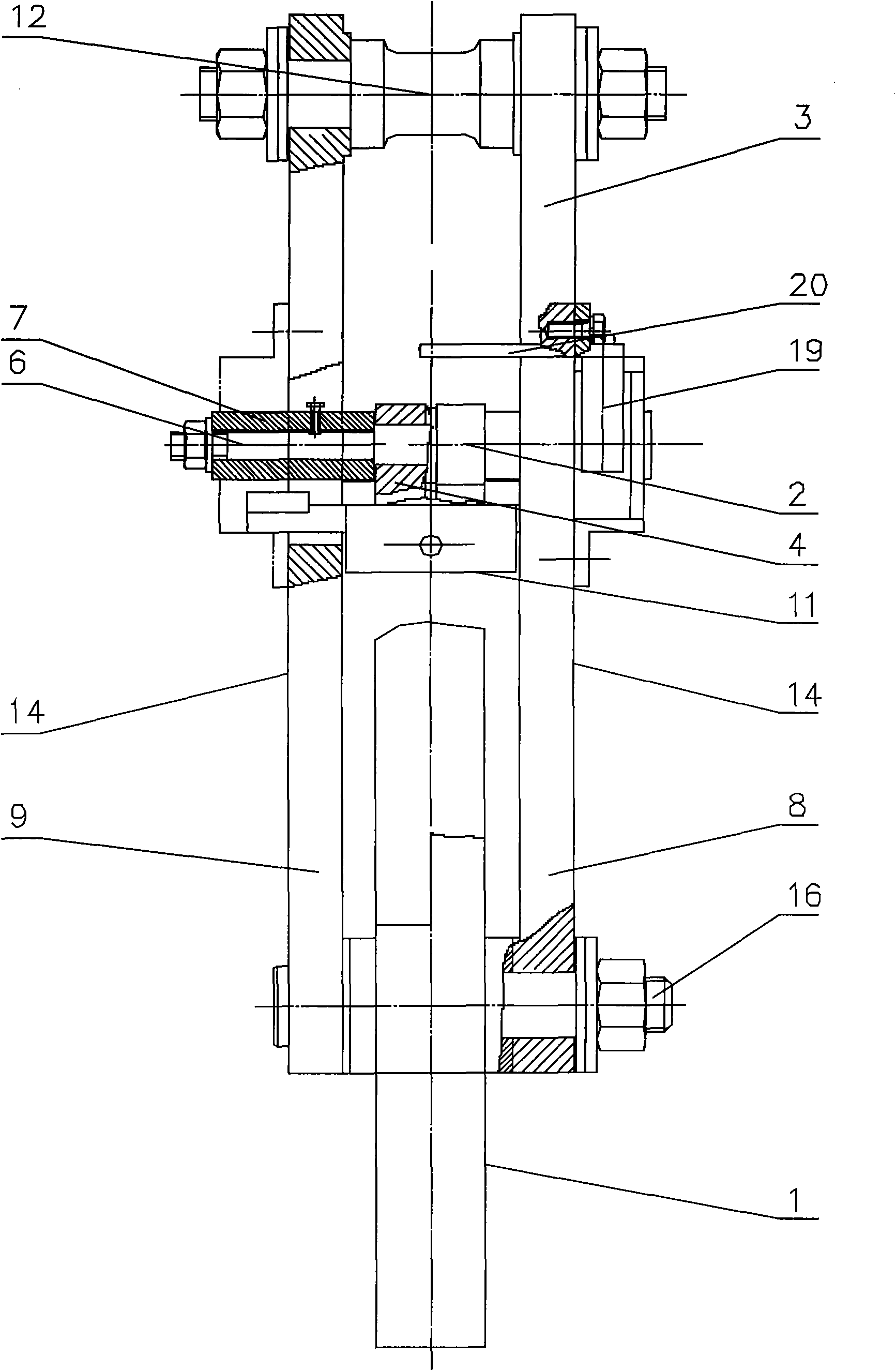
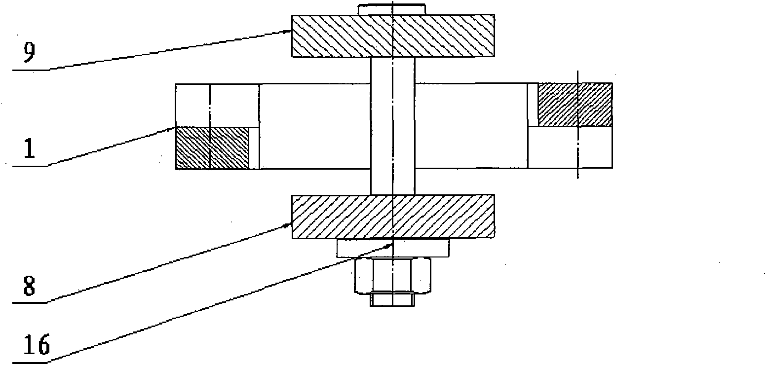
[0035] Such as figure 1 , figure 2 , image 3 As shown, the pincer type uncoupling device of the present invention comprises two symmetrically arranged pincers 1, one end of one of the pincers 1 is hinged with the first connecting rod 2 through the first hinge 3, and one end of the other pincers 1 is connected to the first Two connecting rods 4 are hinged by the second hinge 5, and the other ends of the first connecting rod 2 and the second connecting rod 4 are all connected with the slider shaft 6, and one end of the slider shaft 6 is connected with the opening slider 7, and the slider shaft 6, the opening The slide block 7 is placed in the chute 10 on the first pull plate 8 and the second pull plate 9, and the push rod 11 that can slide along the chute 10 is also provided in the chute 10, and the two ends of the push rod 11 pass through the chute Extending to the outside of the pull plates 8 and 9, the other end of the slider shaft 6 is locked in the self-locking device 1...

Embodiment 2

[0037] On the basis of embodiment 1, the preferred embodiment of the present invention is, as figure 1 , Figure 4-Figure 7As shown, the self-locking frame 13-1 of the self-locking device 13 is located on the outer surface 14 of the first pull plate 8, and the self-locking slider 13-2 is placed in the self-locking frame 13-1, and is connected with the self-locking frame 13-1. Sliding fit, self-locking slide block 13-2 is groove 13-3 shape, and groove 13-3 one end boss is provided with an oblique 13-4, and groove 13-3 is stuck in inner baffle plate 13-5, automatically The groove bottom plate of lock slider 13-2 links to each other with pull bar 13-7, and pull bar 13-7 passes through outer baffle plate 13-6 and links to each other with handle 19, and the other end of handle 19 links to each other with handle linkage 20, and pull bar 13-7 overcoat has Spring 13-8, spring 13-8 is placed between self-locking slide block 13-2 and outer baffle plate 13-6, all the other are identical...

Embodiment 3

[0039] On the basis of embodiment 2, the preferred embodiment of the present invention is, as figure 1 , Figure 8-Figure 10 As shown, the ejector rod 11 is long rod-shaped, and the two ends of the ejector rod extending to the outside of the pull plates 8 and 9 are provided with a slope 11-1 on the surface vertically perpendicular to the pull plate plane, and the slope 11-1 is connected with the self-locking slider. The oblique 13-4 on the 13-2 is slidingly fitted, and the middle of the push rod 11 is provided with a through hole 11-2, and the rest are identical to Embodiment 2.


PUM


Abstract

The invention discloses a clamp unhooking device, belonging to the technical field of the mechanical lifting and drawing equipment. The clamp unhooking device is characterized in that two clamp pieces are arranged symmetrically, one end of each clamp piece is hinged with one end of a connecting rod through a hinge, the other end of the connecting rod is connected with a slider shaft; one end of the slider shaft is connected with an opening slider; the slider shaft and the opening slider are arranged in the chutes of a first pulling plate and a second pulling plate correspondingly, mandrils are also arranged in the chutes; the other end of the slider shaft is locked in a self-locking device; the self-locking device is arranged on the lateral surface of the first pulling plate, one end of the first pulling plate and one end of the second pulling plate are connected through a hinge pin; the other end of the first pulling plate and the other end of the second pulling plate are hinged on the two sides of each clamp piece through hinges, and an unlocking rope and an unhooking rope are arranged between the pulling plates. The clamp unhooking device has simple structure, small opening force, simple and convenient operation, safe and reliable work and accurate unhooking point of fall, and can be used in the fields requiring high centering and accurate unloading position.

Description

technical field [0001] The invention relates to a hook of a lifting and pulling device, in particular to a clamp-type hook uncoupling device, which belongs to the technical field of mechanical lifting and pulling devices. Background technique [0002] The hook used to connect the load in the lifting traction mechanism is very convenient when loading, but it is more troublesome when unloading. As an improved form of the hook, the commonly used decoupling device has two basic forms: clamp type and single hook flip type. The single-hook flip-type decoupling device will generate lateral force when decoupling, causing the decoupling device to swing violently after decoupling. After the heavy object is decoupled, it is easy to cause space drift, the landing point position is inaccurate, and the neutrality is relatively poor. It is mainly used for heavy objects. Occasions where the position of the landing point is not high. Chinese patent document CN92223321.7 discloses an automat...

Claims


Application Information

Patent Timeline
Patent Type & Authority Applications(China)
IPC IPC(8): B66C1/38
Inventor 刘平韦华范仁东陈杰陆伟岗
Owner CEEC JIANGSU ELECTRIC POWER DESIGN INST
Why Eureka
Try Eureka