Processing box and image forming device

A technology for processing boxes and images, which is applied in the fields of electric recording technology using charge patterns, equipment for electric recording technology using charge patterns, and electrography, etc. It can solve problems such as difficulty in loading and unloading, operator hand pinching, burns, etc. Achieve the effect of small pick-and-place force, convenient grip, and prevent burns

Inactive Publication Date: 2011-01-19
ZHUHAI SEINE TECH CO LTD
View PDF6 Cites 8 Cited by
  • Summary
  • Abstract
  • Description
  • Claims
  • Application Information

AI Technical Summary

Problems solved by technology

When the operator removes the process cartridge from the main body of the image forming apparatus, when the operator tries to grab the handle, the hand must be close to the side of the fixing device support frame, which may cause the operator's hand to be burned by the high temperature part of the fixing device support frame
And because the handle on the process box can rotate around the main body of the process box, the force direction of the process box may change at any time, so a large force is needed to disassemble the process box from the main body of the image forming device, and it is easy to cause the operator to Hands pinched by process cartridge handle and laser scanner support frame
With the miniaturization of the image forming apparatus, the installation space provided for the process cartridge in the main body of the image forming apparatus becomes narrower, and the above-mentioned disadvantage of difficult mounting and detachment becomes more and more obvious.

Method used


Image

  • Processing box and image forming device
  • Processing box and image forming device
  • Processing box and image forming device

Examples


Embodiment 1

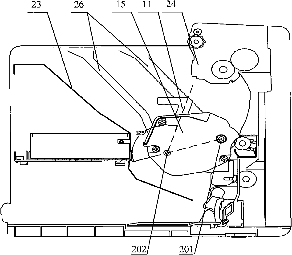
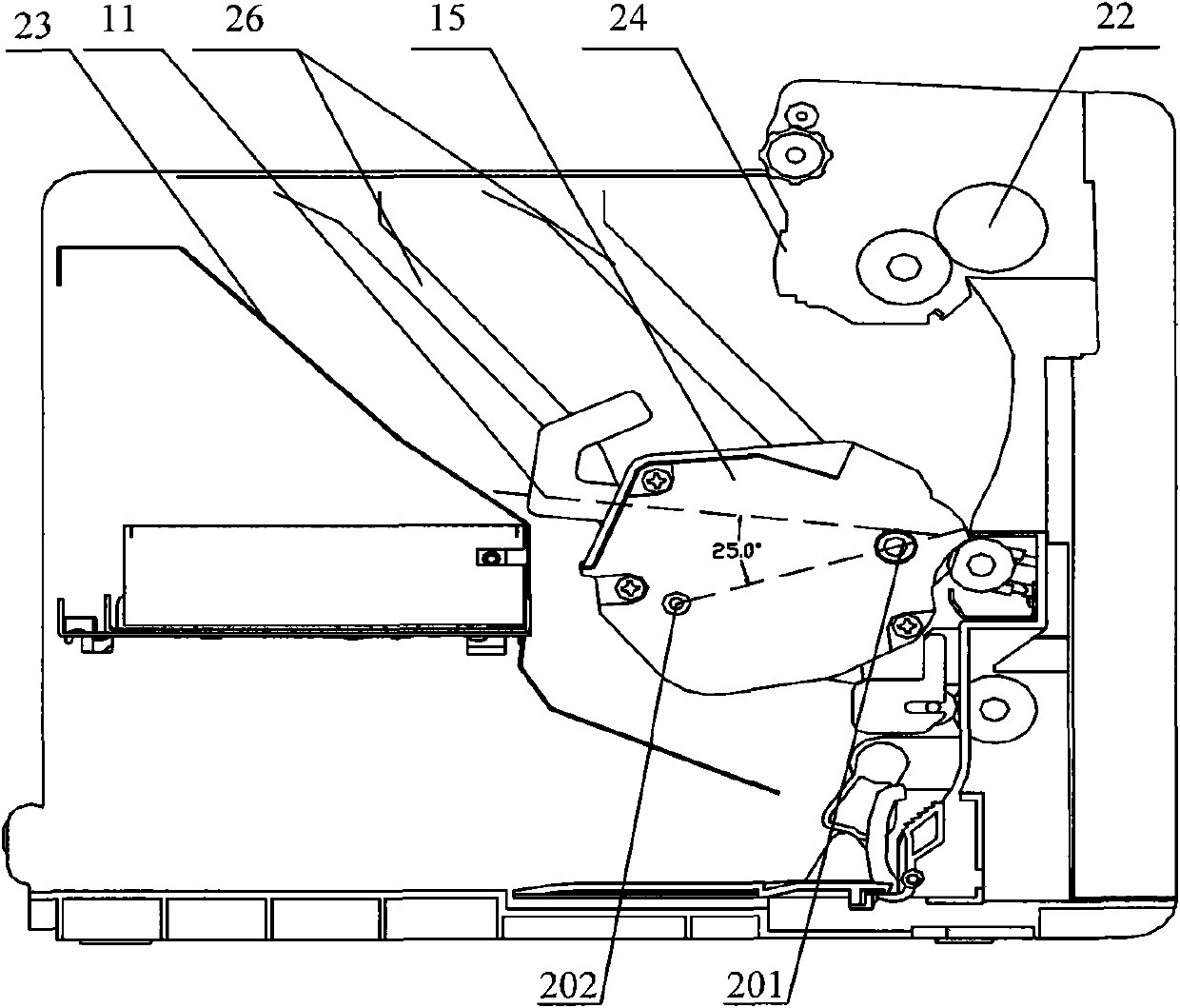
[0028] image 3 It is a schematic diagram of the three-dimensional cut-away structure of the process box provided by Embodiment 1 of the present invention, Figure 4 for image 3 The schematic diagram of the side view structure of the middle process box, the process box includes an upper frame 15, a lower frame 16 and a handle 11, and also includes a photosensitive drum 14 arranged between the upper frame 15 and the lower frame 16, each side end of the process box is respectively A first protrusion 201 and a second protrusion 202 are provided to guide the installation or removal of the process cartridge. An end cap 203 is disposed on the end of the process box, and the first protrusion 201 and the second protrusion 202 are preferably disposed on the end cap 203 . The first protrusion 201 is coaxial with the photosensitive drum 14 , and the second protrusion 202 is located on the downstream side of the first protrusion 201 along the installation direction. The first protrusi...

Embodiment 2

[0033] Figure 5 The schematic diagram of the structure of the process box provided by Embodiment 2 of the present invention. This embodiment is based on Embodiment 1, and the structural shape of the handle 11 is further improved, and the handle 11 is set to a shape that is convenient for the operator to hold. The structure of the handle 11 is specific It includes a connection part 11a, a grip part 11b and a reinforcement part 11c; the connection part 11a is connected between the grip part 11b and the upper frame 15, the connection part 11a is a thin plate structure, and its axis along the length direction coincides with the axis of the handle 11; The thickness of the gripping portion 11b is greater than that of the connecting portion 11a, matching the gripping state of the hand. The gripping portion 11b can be designed as a sash structure or a columnar structure, as long as it is convenient for the operator to hold it stably by hand; The reinforcing part 11c is connected on t...

Embodiment 3

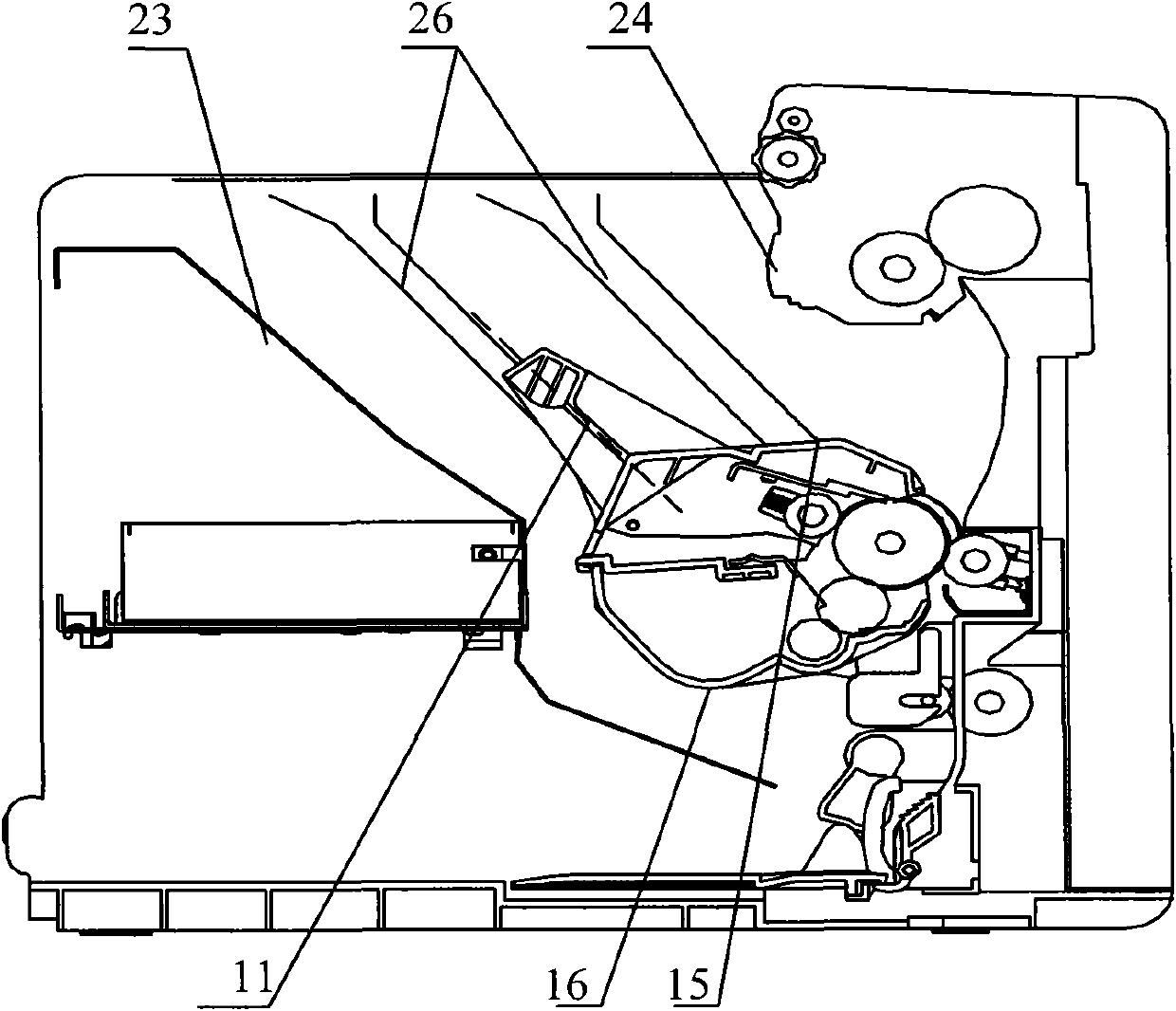
[0036] Figure 6 It is a schematic diagram of a cut-away side view of the image forming apparatus provided by Embodiment 3 of the present invention. like Figure 6 As shown, the image forming device includes a main body of the image forming device, and a guide rail 26 is arranged inside the main body of the image forming device, and the image forming device also includes a process box provided by any embodiment of the present invention, see image 3 and Figure 4 As shown, the first protrusion 201 and the second protrusion 202 of the process cartridge cooperate with the guide rail 26 to guide the installation or removal of the process cartridge.

[0037] Figure 6 Shown is the structure of a typical image forming device. The main body of the image forming device mainly includes a laser scanner 21, a laser scanner supporting frame 23, a fixing device 22, a fixing device supporting frame 24, and a paper feeding structure. The guide rail 26 is provided inside the housing 25 ....


PUM


Abstract

The invention discloses a processing box and an image forming device. The processing box comprises an upper frame, a lower frame, a handle, a first protrusion and a second protrusion, wherein the first protrusion is coaxial with a photosensitive drum, and the second protrusion is arranged at the downstream side of the first protrusion along the mounting direction; the handle is fixedly connected to the upper frame; and an included angle is formed between the axis of the handle deviating from the direction of the upper frame and a central line or an extension line of the two protrusions along the direction directing to the second protrusion from the first protrusion, and the angle range of the included angle is 25-125 degrees. The invention can guarantee that the processing box can be stably, conveniently and safely arranged in the image forming device by an operator, or the processing box can be stably, conveniently and safely taken down from the image forming device.

Description

technical field [0001] The invention relates to the structural technology of a process box in an image forming device, in particular to a process box and an image forming device. Background technique [0002] Image forming devices are devices that form images on recording materials through the principle of electrophotographic imaging, and include various types, such as electrophotographic copiers, laser printers, electrophotographic printers, facsimile machines, and word processors. [0003] The process cartridge is the main part in the image forming apparatus, figure 1 It is a structural schematic diagram of a traditional process cartridge, which mainly includes a process cartridge main body 110 and a handle 111. The process cartridge main body 110 may be composed of an upper frame and a lower frame, and the photosensitive drum is arranged between the upper frame and the lower frame. The handle 111 is rotatably connected to the process cartridge main body 110 via a rotatab...

Claims


Application Information

Patent Timeline
Patent Type & Authority Applications(China)
IPC IPC(8): G03G21/18G03G15/00
Inventor 吴连俊
Owner ZHUHAI SEINE TECH CO LTD
Why Eureka
Try Eureka