Conductive connection for track-riding patient hoists

一种轨道、患者的技术,应用在提升舱领域,能够解决滑车电力丢失等问题

Active Publication Date: 2011-01-19
ARJOHUNTLEIGH MAGOG
View PDF4 Cites 3 Cited by
  • Summary
  • Abstract
  • Description
  • Claims
  • Application Information

AI Technical Summary

Problems solved by technology

A key difficulty is maintaining a reliable conductive connection between the trolley and the track, especially as the trolley travels around bends in the track; at this point, the contact between the trolley and the track is more likely to break away, resulting in a lift Loss of power to the tackle in the cabin system

Method used


Image

  • Conductive connection for track-riding patient hoists
  • Conductive connection for track-riding patient hoists
  • Conductive connection for track-riding patient hoists

Examples


Embodiment Construction

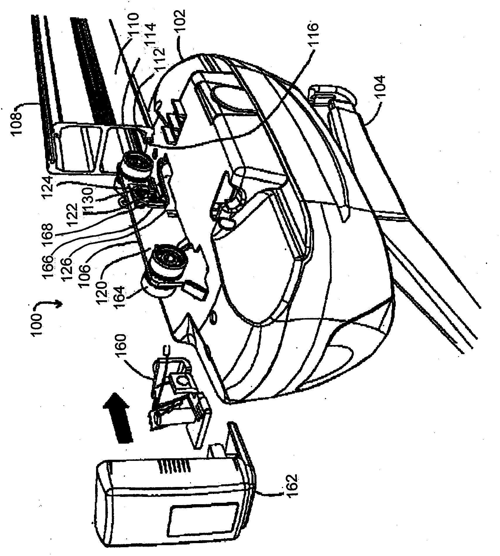
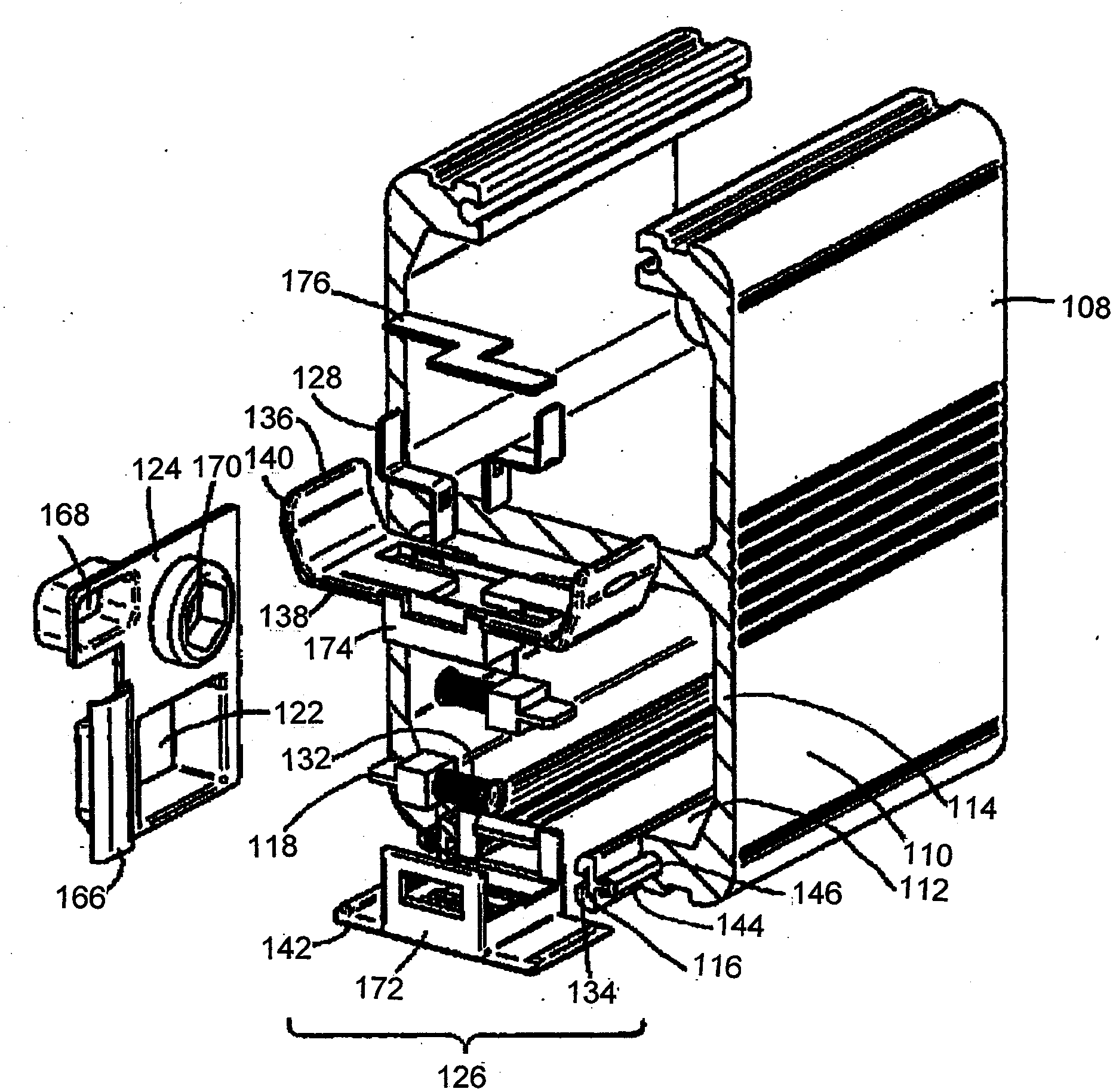
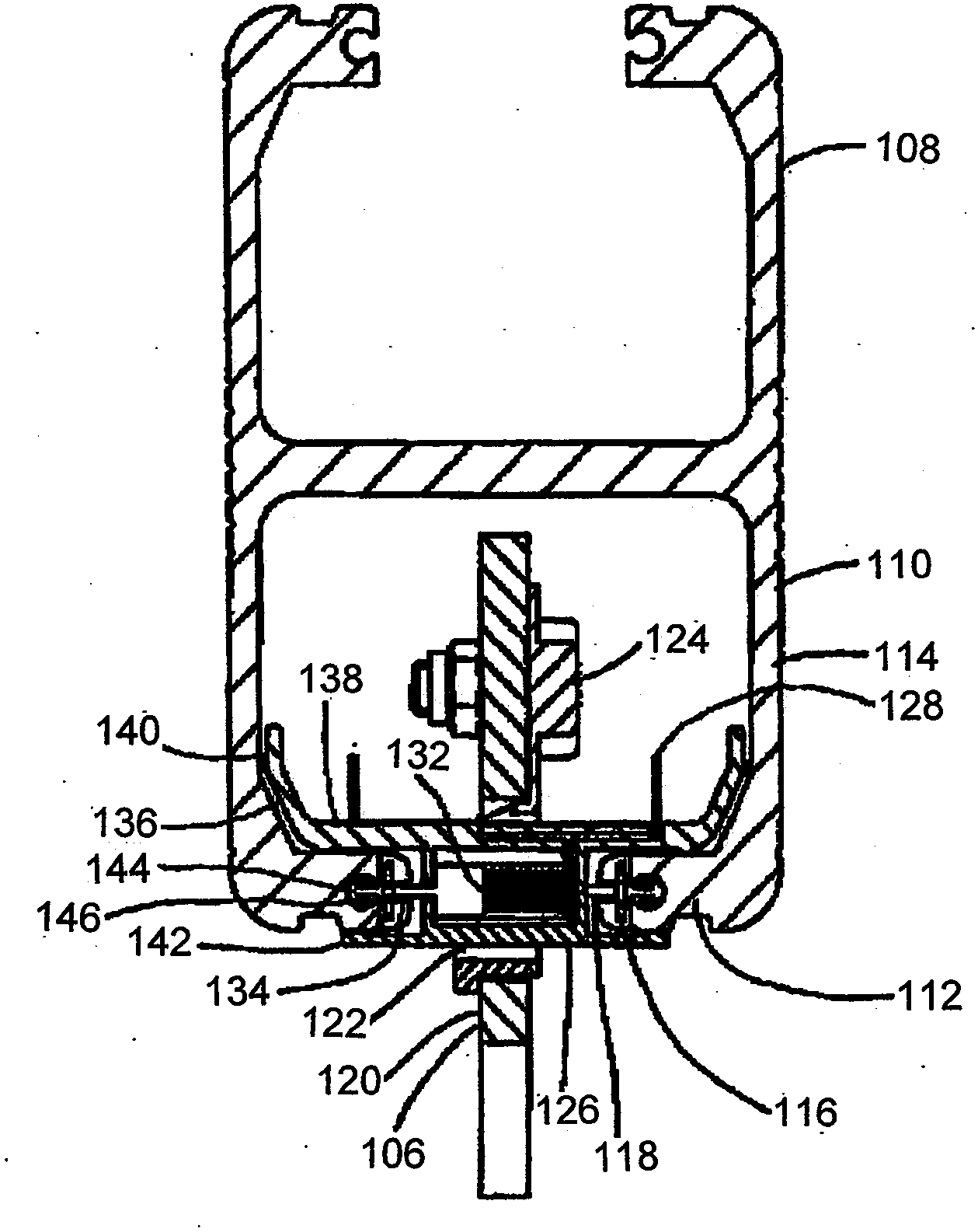
[0016] Elaborating on the above discussion, the riser 102 and track 108 illustrated in all drawings were developed by BHM Medical Inc. (Magog, Quebec, Canada), which offers several different track and riser configurations. (Magog, QC, Canada)) was adapted from the KWIK track and lift cabin system. The example rails 108 illustrated in all figures are configured in a manner similar to a pair of C-channels joined with their mouths facing in opposite directions, as best seen in image 3 middle. Usefully, some versions of the KWIKtrack track have included connection slots 146 that can be used to receive the connection tongues 144 of the track conductors 116, as previously described. Accordingly, the track 108 is easily constructed by installing only the track conductor 116 therein. Once the track conductor 116 is installed in the track 108, it can be moved by placing the lift cabin trolley 106 on the track side 110 (e.g. figure 1 As illustrated in ) to install the hoist cabin tr...


PUM


Abstract

A patient hoist is provided on a trolley which tides along a track, with the hoist being powered by a conductor extending along the track. A contact carrier is loosely fit within the trolley, and it bears a contact which elastically biased against the track conductor, with die contact being in electrical communication with the hoist: The contact carrier is tree to laterally displace with respect to the trolley so that it (and its contact) follows the contour of the track, with the contact remaining in electrical communication with the track conductor.

Description

technical field [0001] This document is concerned with the following inventions, which relate generally to lift cabins mounted on ceiling-mounted or other tracks to various locations for lifting or transporting patients or equipment, and more particularly to along-track Lifting cabins that require electrical power supply at various locations. Background technique [0002] Ceiling-mounted or other rail-mounted lift pods are commonly used in hospitals and other care centers and in the homes of people with mobility impairments to transport people and / or equipment to different areas (e.g., from bed to bathroom) . Examples of such lift bays are provided in, for example, U.S. Patent 7,237,491 to Faucher et al., International (PCT) Patent Application Publication WO 88 / 09159, and others cited in and citing these references. Patent pending. Such lift cabins are usually electric and they may be mounted on rails via manually driven trolleys or trolleys which are themselves electrica...

Claims


Application Information

Patent Timeline
Patent Type & Authority Applications(China)
IPC IPC(8): A61G7/14
CPCB66C7/08A61G7/1042
Inventor 马丁·福谢迈克尔·莫利纳米歇尔·科里沃乔斯林·帕特里
Owner ARJOHUNTLEIGH MAGOG
Why Eureka
Try Eureka