Rubber plate for railway level crossings and rubber hold-down strip thereof

A technology of rubber beading and track boards, which is applied in the field of rubber beading and rubber beading filled between the rubber bead and the track, which can solve the problems of endangering the safety of motorcycle riders, unevenness, and slipping of motorcycle tires And other issues

Inactive Publication Date: 2012-09-19
CHINA STEEL
View PDF0 Cites 1 Cited by
  • Summary
  • Abstract
  • Description
  • Claims
  • Application Information

AI Technical Summary

Problems solved by technology

General railway level crossing track needs to be provided with groove shape rim groove 11 in two steel rails 10 inner sides because of the railway vehicle wheel appearance size that cooperates to use, in order to facilitate the safe running of railway vehicle, unlikely to derail; Create pit-like obstacles, form potential danger factors, and endanger the safety of people and motorcycle riders at any time
[0003] In addition, some level crossing roads are paved with asphalt tar sand, but because the road surface is often rolled by heavy road vehicles, the tar sand on the inner rim of the track often falls off, resulting in potholes and unevenness of the road surface; Accidents where motorcycle tires get caught in wheel rim grooves and slip more often
[0004] In view of the above situation, some railway level crossings are changed to laying rubber track slabs, and rubber beading is filled in the recessed position of the rim groove of the oblique level crossing, and the two ends of the rubber track slab are fixed with bolts to prevent the treadmill wheels from being caught in the wheels. Accidents occur in the edge groove; but although the rubber track plate and the rubber bead are fixed with bolts, when heavy vehicles pass by, the bolts are relatively easy to loosen and fall off under pressure, and the rubber bead protrudes from the level crossing road surface, endangering the motorcycle. knight safety

Method used


Image

  • Rubber plate for railway level crossings and rubber hold-down strip thereof
  • Rubber plate for railway level crossings and rubber hold-down strip thereof
  • Rubber plate for railway level crossings and rubber hold-down strip thereof

Examples


Embodiment Construction

[0052] In order to have a further understanding of the characteristics of the present invention, now cooperate with relevant embodiments and drawings to describe in detail as follows:

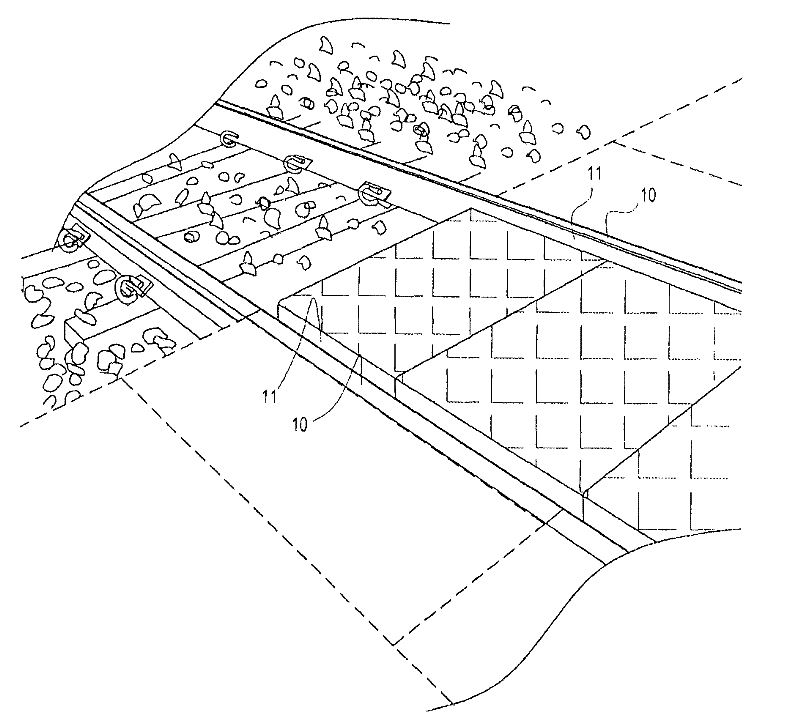
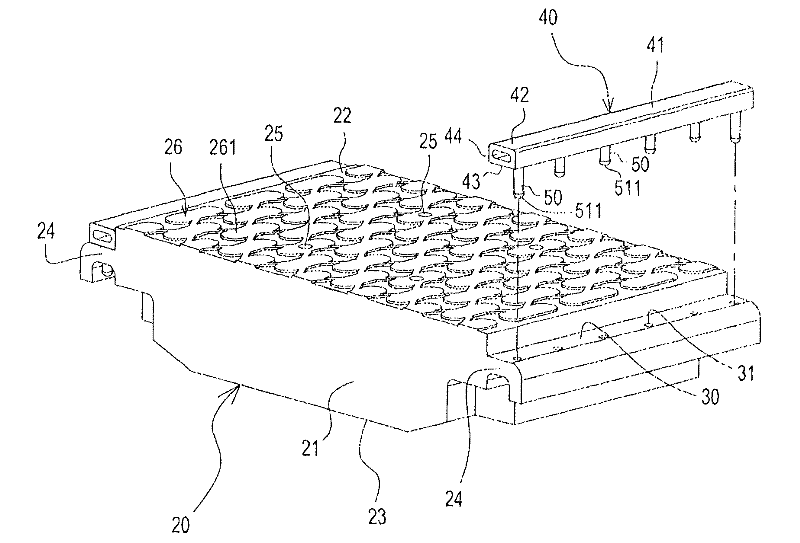
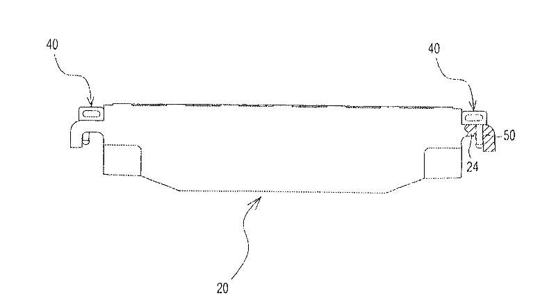
[0053] First please refer to figure 2 The three-dimensional exploded view of the rubber road plate and rubber bead embodiment of the present invention shown in the drawing, image 3 The schematic diagram of the combination of the embodiment of the rubber track plate and the rubber bead of the present invention is shown. The rubber track 20 includes: a track main body 21 and two grooves 30 on the outside. The main body 21 of the road plate has a top surface 22 and a bottom surface 23. The main body 21 of the road plate has a shoulder 24 corresponding to each outer side of the two rails A. The main body 21 of the road plate is also provided with at least one drainage piece 25, and the water drainage piece 25 can be a hole or groove structure and runs through the entire track plate main body 21....


PUM


Abstract

The invention discloses a rubber plate for railway level crossings and a rubber hold-down strip thereof, which are laid between two rails of the railway level crossing. The rubber plate comprises a plate main body and two concave trenches, wherein the plate main body is provided with a shoulder on each outer side of the two rails, and also is provided with at least one row of water fittings in parallel; the two concave trenches are respectively arranged on one side of each shoulder and respectively formed by the height difference between the top surface and the shoulder; and a plurality of combining holes are arranged in each concave trench. The rubber hold-down strip has the structure that the hold-down strip body is embedded in the concave trench of the rubber plate; a hollow buffer chamber is formed between the top surface and the bottom surface of the hold-down strip body; and a plurality of fixed bars are formed on the bottom surface of the hold-down strip body, and correspondingly inserted into the combining holes of the rubber plate.

Description

technical field [0001] The invention relates to a rubber track slab of a railway level crossing and its rubber bead, in particular to a rubber track slab with a drainage structure and the rubber bead pressed between the rubber track slab and the track. Background technique [0002] Please refer to the schematic diagram of road slab laying of railway level crossing shown in FIG. 1 . General railway level crossing track needs to be provided with groove shape rim groove 11 in two steel rails 10 inner sides because of the railway vehicle wheel appearance size that cooperates to use, in order to facilitate the safe running of railway vehicle, unlikely to derail; Cause pit-like obstacles, form a potential risk factor, and endanger the safety of people and motorcycle riders at any time. [0003] In addition, some level crossing roads are paved with asphalt tar sand, but because the road surface is often rolled by heavy road vehicles, the tar sand on the inner rim of the track ofte...

Claims


Application Information

Patent Timeline
Patent Type & Authority Patents(China)
IPC IPC(8): E01C9/04E01C11/02
Inventor 侯碧松谢锡毅萧宜峯林纯逸
Owner CHINA STEEL
Why Eureka
Try Eureka