Backlight module and liquid crystal display

A liquid crystal display and backlight module technology, applied in the directions of instruments, optics, light guides, etc., can solve the problems of increased production costs, easy lifting or separation, and measurement of ripples on the light guide plate, so as to improve uneven projection or light leakage and save energy. Material cost, compact structure

Inactive Publication Date: 2011-01-26
AU OPTRONICS (SUZHOU) CORP LTD +1
View PDF6 Cites 24 Cited by
  • Summary
  • Abstract
  • Description
  • Claims
  • Application Information

AI Technical Summary

Problems solved by technology

However, this backlight module is easy to be tilted or detached when the adhesiveness of the adhesive tape is reduced, thereby affecting the optical effect of the light-emitting diode; between the light guide plate and the back plate) will be stuck together, and the problem of ring measurement ripple of the light guide plate will occur at this time; in addition, the use of tape in front of the light emitting surface of the LED may affect the light utilization efficiency; moreover, a large amount of tape is used , the production cost increases

Method used


Image

  • Backlight module and liquid crystal display
  • Backlight module and liquid crystal display
  • Backlight module and liquid crystal display

Examples


Embodiment Construction

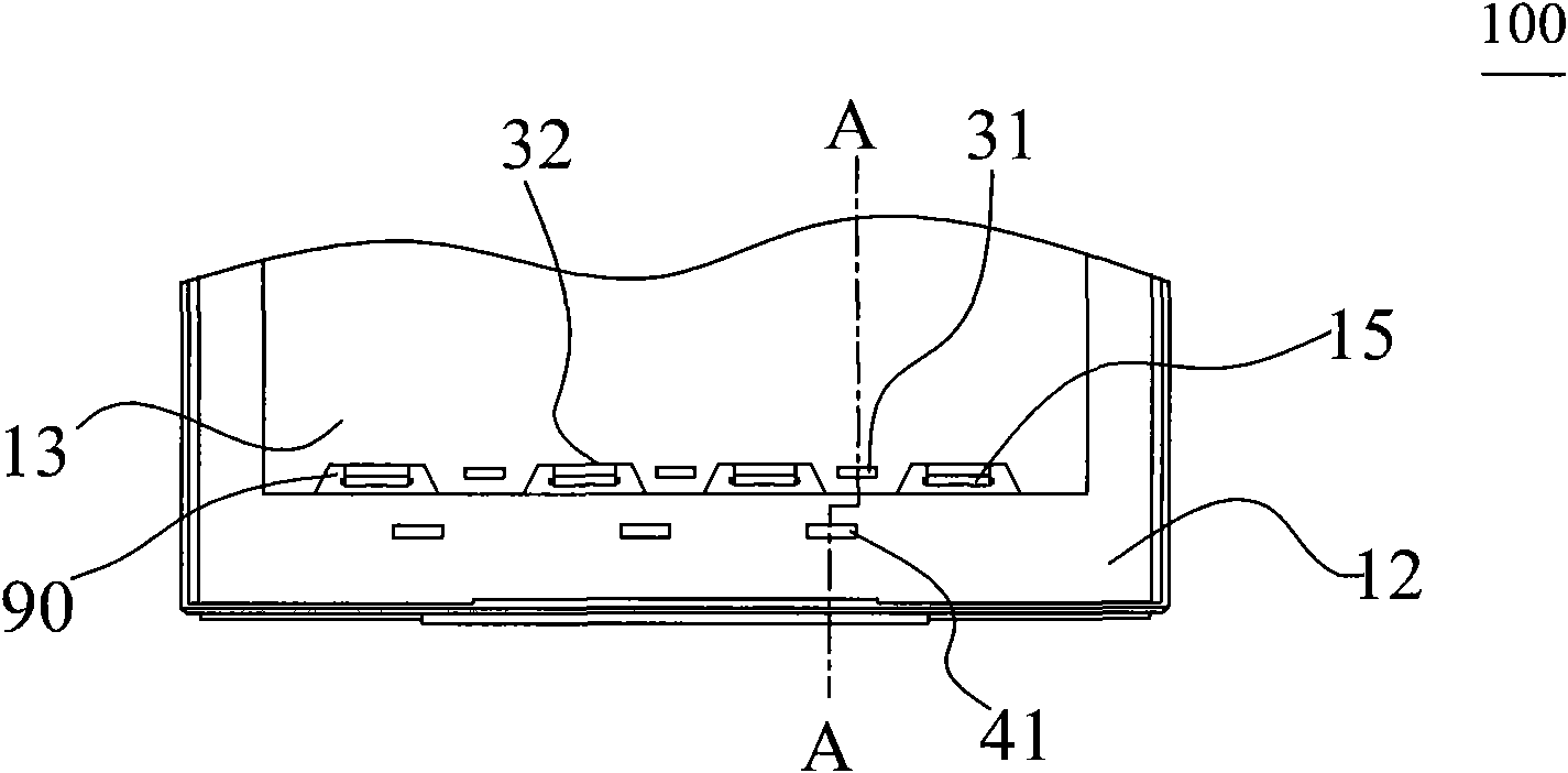
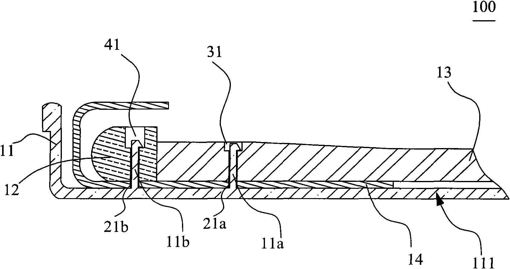
[0021] See figure 2 with image 3 , figure 2 It is a schematic top view of the first preferred embodiment of the backlight module of the present invention, image 3 for figure 2 A schematic cross-sectional view of line A-A. The present invention provides a backlight module 100 , which includes a backplane 11 , a frame 12 , a light guide plate 13 and a light source module. The light source module includes a circuit board 14 and a plurality of light emitting diodes 15 . The light guide plate 13 has a light incident surface 32, wherein in this embodiment, one side of the light incident surface 32 of the light guide plate 13 has a plurality of grooves 90, the grooves 90 are used to accommodate the light emitting diodes 15, of course, the other In an embodiment, the groove 90 may also be located on a side of the frame body 12 facing the light-incident surface 32 . In addition, the light guide plate 13 has at least one first through hole 31 . The frame 12 is disposed on the...


PUM


Abstract

The invention discloses a backlight module and a liquid crystal display. A frame, a circuit board and a back board of the backlight module are fixed through a first fixing member, meanwhile, a light guide board, the circuit board and the back board are fixed through a second fixing member, a light-emitting diode is arranged between the light-incident surface of the light guide board and the frame so that the circuit board of a light source module is restrained in the horizontal direction and the vertical direction, thereby solving the problems of easy bounce and deflection of the light-emitting diode and improving the phenomenon of nonuniform projection or light leakage of the light-emitting diode. Furthermore, the circuit board of the light source module is fixed and located without using an adhesive tape, thereby saving material cost, having compact structure and being conveniently assembled.

Description

technical field [0001] The invention relates to a backlight module of a liquid crystal display, in particular to a backlight module using a light-emitting diode as a light source, and a liquid crystal display using the backlight module. Background technique [0002] See figure 1 , figure 1 It is a schematic diagram of a prior art backlight module. In the prior art, the backlight module 1 provides a backlight source for a liquid crystal display panel of a liquid crystal display. The backlight module 1 includes a light source module, a light guide plate 30, a plastic frame 40 and a backplane 10. The light source module includes a circuit board 20 and A light emitting diode (LED) 50 is electrically disposed on the circuit board 20 . When assembling the backlight module 1 , the light emitting diode 50 is snapped into the placement groove formed between the plastic frame 40 and the light guide plate 30 in the backlight module 1 . Wherein, the circuit board 20 may be a flexibl...

Claims


Application Information

Patent Timeline
Patent Type & Authority Applications(China)
IPC IPC(8): F21S8/00F21V8/00F21V17/10F21V19/00F21V17/12F21V7/00G02F1/13357F21Y101/02
Inventor 陈新春郑仲豪余康
Owner AU OPTRONICS (SUZHOU) CORP LTD
Why Eureka
Try Eureka