Method for generating demodulating reference signal and device thereof

A technology of reference signal and symbol position, applied in the field of demodulation reference signal, which can solve problems such as high overhead

Inactive Publication Date: 2011-01-26
CHONGQING WIRELESS OASIS COMM TECHCO
View PDF2 Cites 24 Cited by
  • Summary
  • Abstract
  • Description
  • Claims
  • Application Information

AI Technical Summary

Problems solved by technology

For example, in the LTE system, when there are 3 cells under the same site, and each cell has 4 transmit antennas, the overhead caused by the t

Method used


Image

  • Method for generating demodulating reference signal and device thereof
  • Method for generating demodulating reference signal and device thereof
  • Method for generating demodulating reference signal and device thereof

Examples


Embodiment Construction

[0062] The present invention adapts to the above-mentioned problems in the prior art by generating a reference signal (or a demodulation reference signal). In the following description, the terms: reference signal, demodulation reference signal, and pilot signal have the same concept.

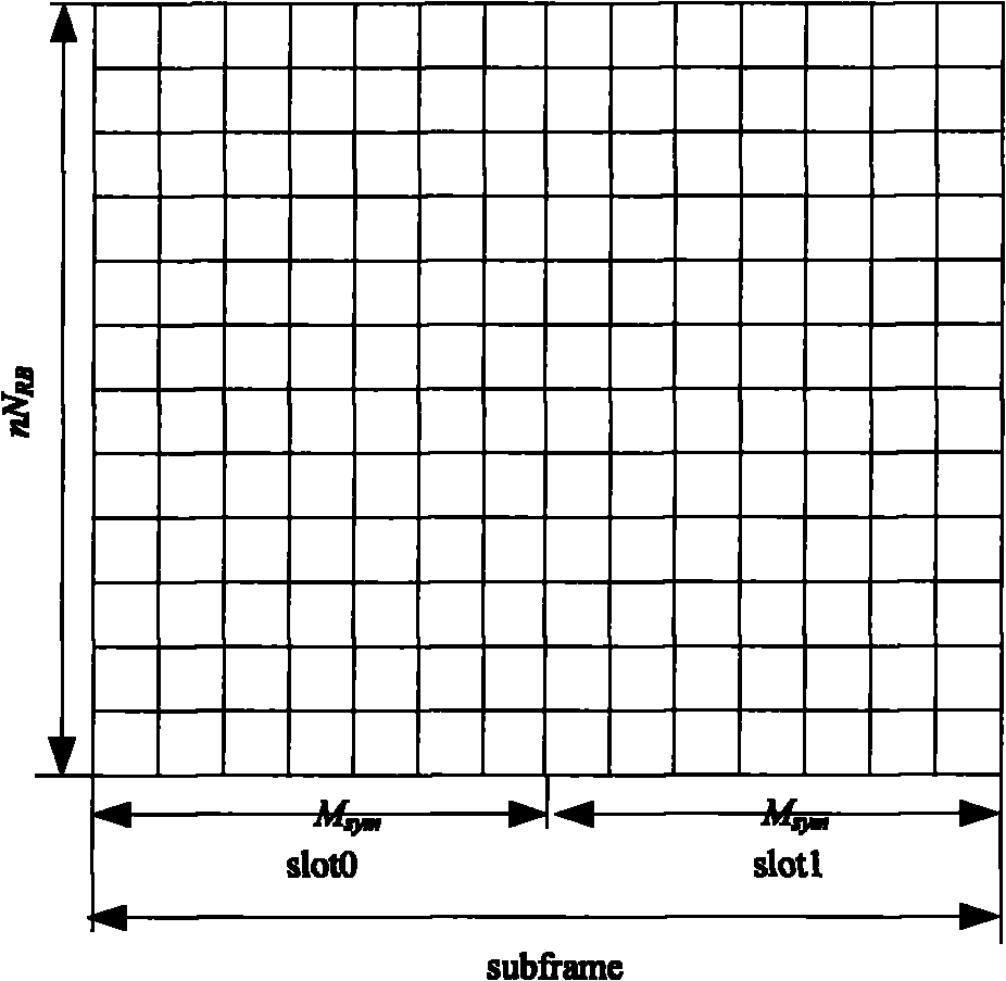
[0063] figure 1 It shows a basic unit of signal transmission suitable for the reference signal of the present invention, which is a time slot and subframe structure of a general two-dimensional time-frequency unit. Each time slot (slot) occupies equal length M in time sym symbols, occupying nN in the frequency domain RB subcarriers. RB is (length N RB ) is a basic unit for the system to allocate resources in the frequency domain direction, and slot is a basic unit for the system to allocate resources in the time domain direction.

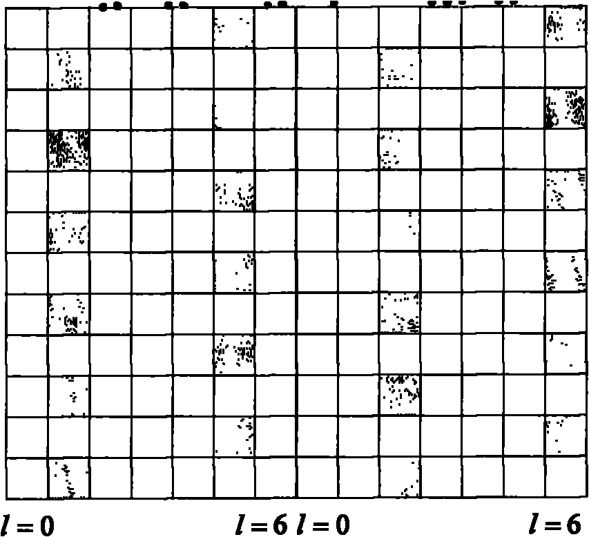
[0064] The basic method of the present invention is to place the pilot symbols at appropriate positions in the multi-carrier time-frequency two-dimensional stru...


PUM


Abstract

The invention discloses a demodulating reference signal design method and a device thereof, including a demodulating reference signal design pattern, a demodulating reference signal scrambling scheme, an allocation scheme of demodulating reference signal in single cell and an allocation scheme of the demodulating reference signal among multiple cells. The invention also provides a channel estimation method corresponding to the allocation scheme. The invention is not only applicable to single cell, but also to implementation of demodulating reference signal among multiple cells.

Description

technical field [0001] The invention relates to a demodulation reference signal used in a cellular mobile communication system, in particular to a generation method of a coherent demodulation reference signal used in a multi-carrier system and a corresponding channel estimation method. Background technique [0002] A multi-carrier system, such as an Orthogonal Frequency Division Multiplexing (OFDM) system, is a mainstream multi-carrier technology in wireless communication systems after the third generation (3G). In an OFDM system, data is usually modulated on subcarriers in the OFDM frequency domain in the form of modulation symbols, and then transformed into sampling points in the time domain by inverse fast Fourier transform (IFFT) to form a baseband transmission signal. After the signal is transmitted by radio frequency (RF), the electromagnetic wave reaches the receiver after passing through the wireless channel of the air interface. The goal of the receiver is how to c...

Claims


Application Information

Patent Timeline
IPC IPC(8): H04L27/26H04L25/03H04B1/707
Inventor 黎超段世平肖业平
Owner CHONGQING WIRELESS OASIS COMM TECHCO
Why Eureka
Try Eureka