Belt-type feeder

A feeder and ratchet technology, applied in the direction of electrical components, electrical components, etc., can solve the problems of vibration, flying out, protrusion, and inability to use the adsorption nozzle to absorb, etc., to achieve reliable positioning and stable attitude

Active Publication Date: 2011-01-26
JUKI CORP
View PDF5 Cites 5 Cited by
  • Summary
  • Abstract
  • Description
  • Claims
  • Application Information

AI Technical Summary

Problems solved by technology

[0012] In the tape feeder 10 as described above, there is a problem that, since the carrier tape T moves intermittently to the component supply portion (attraction position) 12, vibration (shock) is applie

Method used


Image

  • Belt-type feeder
  • Belt-type feeder
  • Belt-type feeder

Examples


Example Embodiment

[0040] Hereinafter, embodiments of the present invention will be described in detail with reference to the drawings.

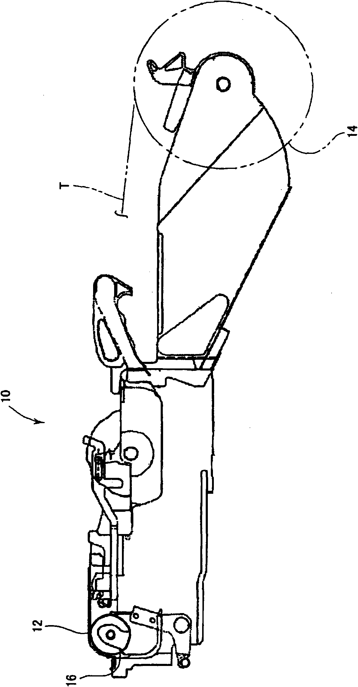
[0041] The tape feeder 10 of this embodiment is similar to the above figure 1 , figure 2 The basic structure of the device shown is the same. Therefore, detailed descriptions of the same parts are omitted.
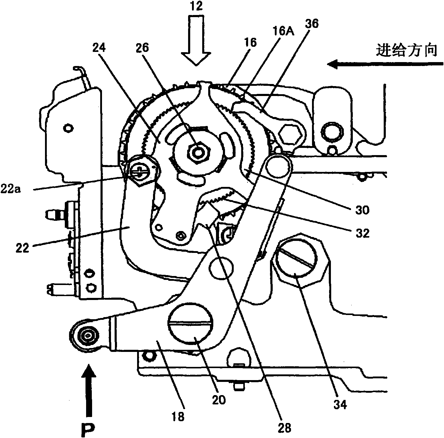
[0042] in Figure 7 , Figure 8 In the above-mentioned stopping pawl 36 as a pawl member, the engaging portion 40 at the tip has an engaging surface 43 composed of two flat surfaces 41 and 42 intersecting in the tip direction, and the groove-shaped ratchet teeth 32 The ratchet 30 has a circumferential end surface 30A formed at equal intervals, and has a tooth surface 53 composed of two flat surfaces 51 and 52 whose front ends intersect in the axial center direction.

[0043] The ratchet teeth 32 and the engagement portion 40 at the front end of the pawl 36, refer to Picture 9 As shown in (A) and (B), the engagement surface angle α formed by the engagement surf...


PUM


Abstract

The invention provides a belt-type feeder which alleviates impact between ratchet teeth and a retaining pawl which rotate along the interval of chain wheels, and prevents tripping out of an electrical component. In the belt-type feeder, the retaining pawl is provided with a blocking surface formed by two planes crossed at a front end direction by a blocking part at the front end; and ratchet teeth form teeth surfaces at interval on a circumferential end surface of the ratchet; the teeth surfaces have two planes which are crossed on a central direction of a shaft of the front end; the angle of the blocking surface of the blocking part is larger than the angle of the teeth surface; and the blocking part is formed that: when blocking with the ratchet teeth at maximum, the distance from a vertex position crossed on the blocking surface to a reference position formed by connecting two intersecting points between the teeth surface and the circumferential end surface of the ratchet is 1/2 longer than the distance from the reference position to the vertex position crossed with the teeth surface.

Description

technical field [0001] The present invention relates to a tape feeder which intermittently feeds the carrier tape while rotating a sprocket for inserting pins into feed holes provided at equal intervals on the carrier tape by means of a coaxial ratchet. While supplying, the stored electronic components are supplied to a predetermined position. Background technique [0002] In order to mount (mount) electronic components on a substrate to be positioned, a mounting device (component mounting device) is generally used. [0003] In such a mounting device, in order to mount various electronic components, a plurality of tape feeders storing different electronic components are mounted, and each electronic component is supplied to a predetermined position. [0004] For example figure 1 As shown, the tape feeder 10 is provided with: a component supply part 12 at a predetermined position, which is formed at the front end; a reel 14, which is installed at the rear end, and pre-winds ...

Claims


Application Information

Patent Timeline
IPC IPC(8): H05K13/02
Inventor 谷口史之
Owner JUKI CORP
Why Eureka
Try Eureka