Door mirror device
A rearview mirror and outer lens technology, which is applied in the field of rearview mirror devices, can solve the problems of low designability and non-continuous light-emitting of light guides, and achieve the effect of improved designability
- Summary
- Abstract
- Description
- Claims
- Application Information
AI Technical Summary
Problems solved by technology
Method used
Image
Examples
no. 1 approach
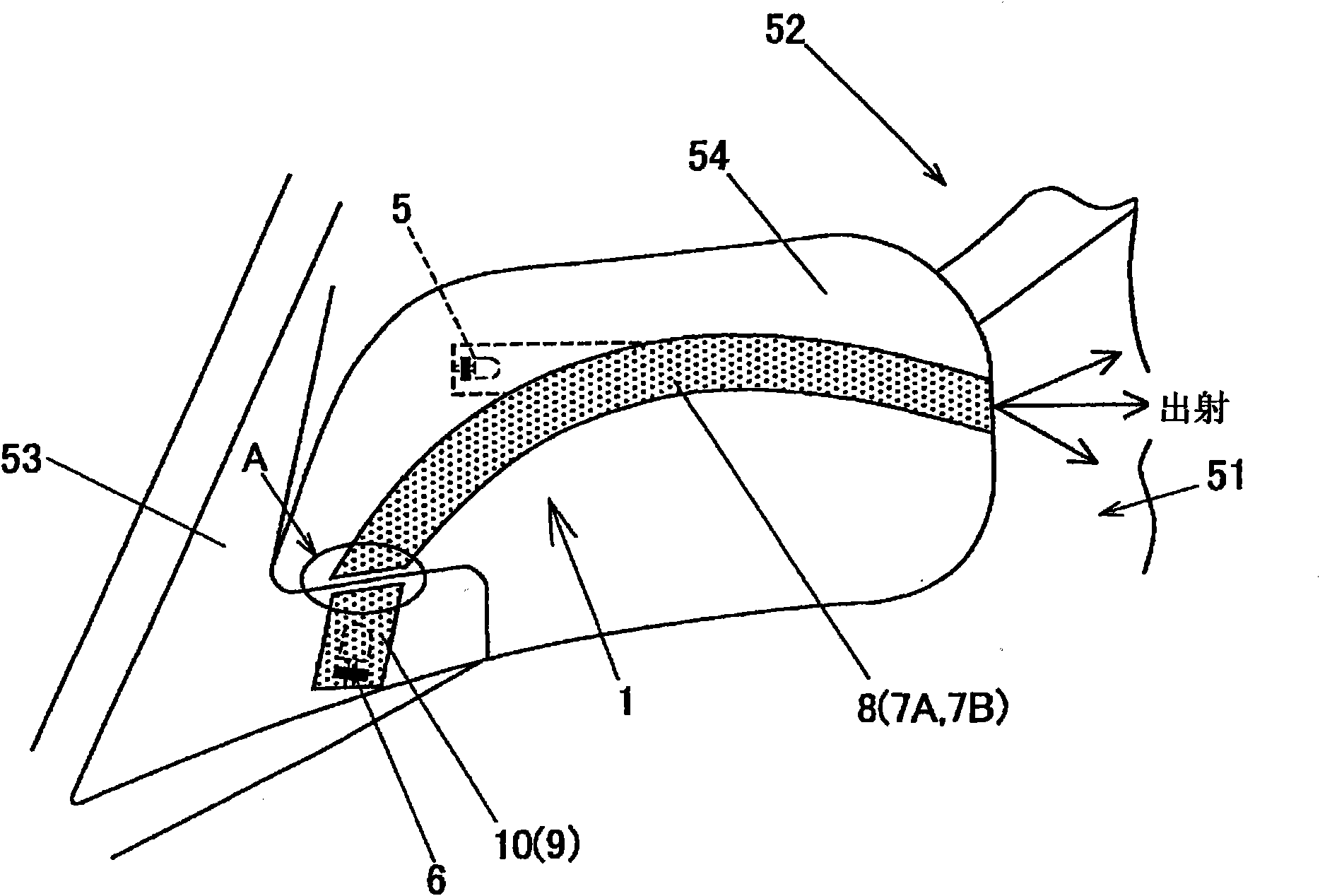
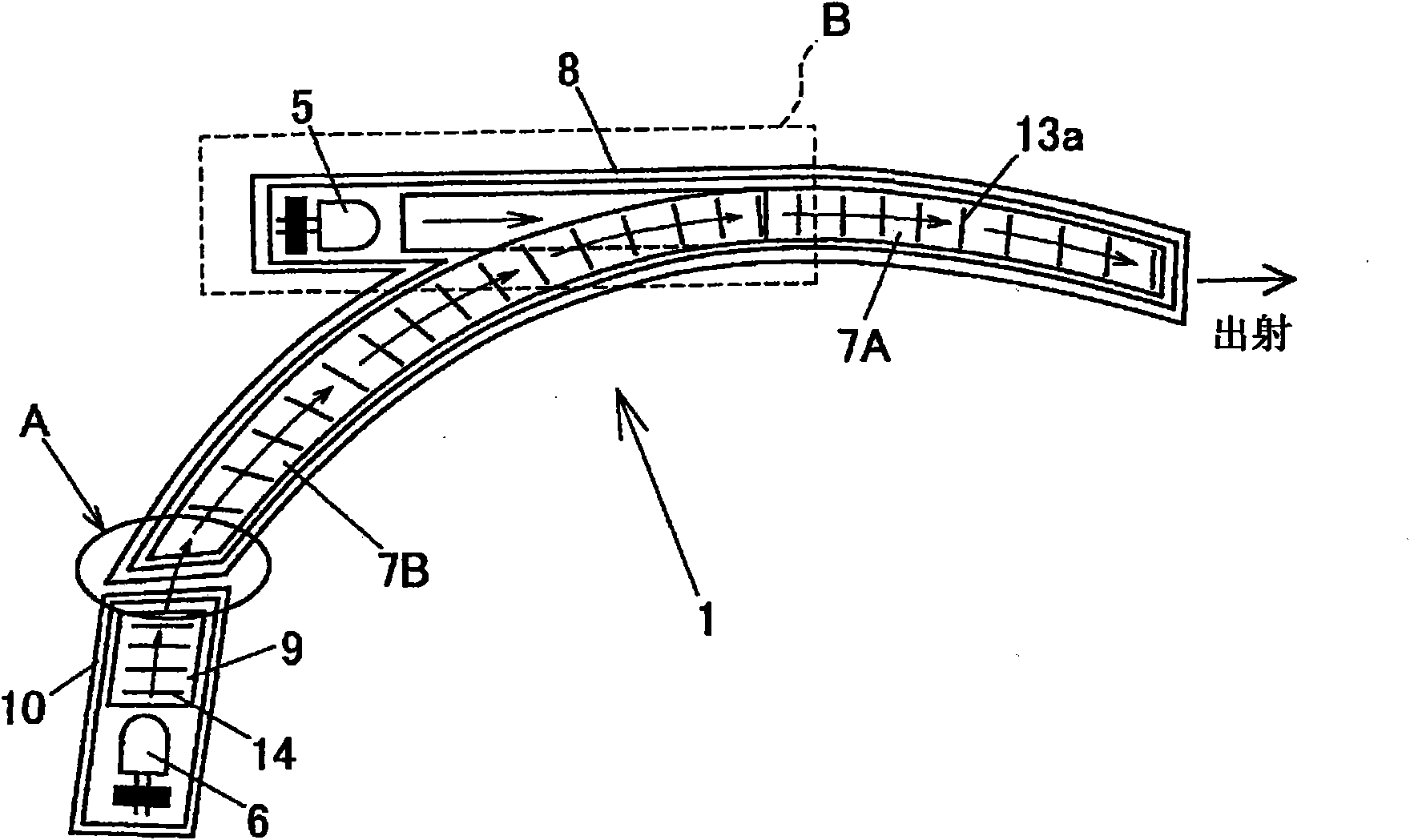
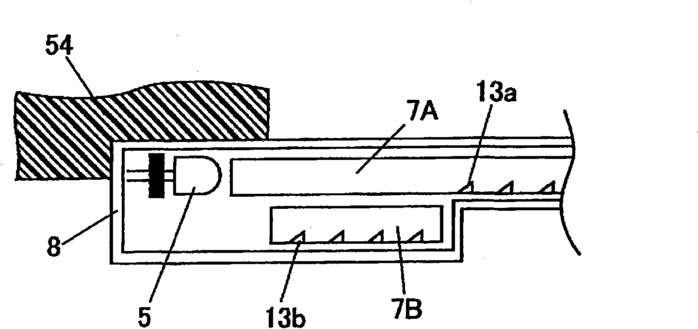
[0036] Next, a first embodiment of the present invention will be described with reference to the drawings. figure 1 It is an overall view of the door mirror device and the periphery of the door mirror according to the first embodiment. figure 2 It is a configuration diagram of the rearview mirror device seen from the rear. image 3 Yes figure 2 Longitudinal sectional view of area B in dotted line. Figure 4 It is a schematic side view of three light-emitting light guides.
[0037] like figure 1 As shown, the rearview mirror of an automobile is reversibly attached to a rearview mirror support part 53 provided at the position of a window 52 of a door 51, and has a shield part 54 that supports a mirror main body (not shown). The shield portion 54 is a synthetic resin case whose outer wall is curved.
[0038] The door mirror device 1 of the first embodiment includes light sources 5 , 6 , light-emitting light guides 7A, 7B, 9 , and outer lenses 8 , 10 .
[0039] The light s...
no. 2 approach
[0054] Next, a rearview mirror device 1A according to a second embodiment in which the above-described first embodiment is partially modified will be described with reference to the drawings. Figure 5 is the rearview mirror device of the second embodiment and figure 2 Quite a graph. In addition, the same code|symbol is attached|subjected to the same structure as the above-mentioned embodiment, and description is abbreviate|omitted.
[0055] Figure 5 The shown rearview mirror device 1A is the above-mentioned figure 2 The shown light-emitting light guide body 7A, 7B is an integrated device. which is, Figure 5 The shown mirror arrangement has two light-emitting light guides 7 , 9 .
[0056] Figure 5 The light-emitting light guide body 7 of the shown rearview mirror device 1A is provided with a branch portion 7 a that branches off in the middle. The light emitting light guide 7 is formed in a curved shape. One end portion of the light-emitting light guide 7 is disposed...
no. 3 approach
[0060] Next, a rearview mirror device 1B according to a third embodiment in which the above-described embodiment is partially modified will be described with reference to the drawings. Image 6 It is an overall view of the door mirror device and the periphery of the door mirror according to the third embodiment. Figure 7 is the third embodiment of the rearview mirror device and figure 2 Quite a graph. In addition, the same code|symbol is attached|subjected to the same structure as the above-mentioned embodiment, and description is abbreviate|omitted.
[0061] Image 6 and Figure 7 The light-emitting light guide body 7 of the shown rearview mirror device 1B is branched at two places, and is provided with two branch portions 7a, 7b. The light source 6 is provided at the end of the branch portion 7b. That is, in the door mirror device 1B, the light source 6 is also disposed on the shield portion 54 .
[0062] In the rearview mirror device 1B of the third embodiment, when ...
PUM
 Abstract
Description
Claims
Application Information
 - R&D
- Intellectual Property
- Life Sciences
- Materials
- Tech Scout
- Unparalleled Data Quality
- Higher Quality Content
- 60% Fewer Hallucinations
Browse by: Latest US Patents, China's latest patents, Technical Efficacy Thesaurus, Application Domain, Technology Topic, Popular Technical Reports.
© 2025 PatSnap. All rights reserved.Legal|Privacy policy|Modern Slavery Act Transparency Statement|Sitemap|About US| Contact US: help@patsnap.com


