Aircraft engine assembly comprising an annular load-transfer structure surrounding the central casing of a turbojet engine

An annular structure, turbojet technology, applied in the direction of machines/engines, aircraft parts, jet propulsion devices, etc., can solve the problems of annular structure and/or center shell deformation, unoptimized connecting rod arrangement, etc., to achieve optimal mechanical connection. Effect

Inactive Publication Date: 2011-01-26
AIRBUS OPERATIONS (SAS)
View PDF7 Cites 6 Cited by
  • Summary
  • Abstract
  • Description
  • Claims
  • Application Information

AI Technical Summary

Problems solved by technology

[0008] However, in prior art solutions, the arrangement of the aforementioned connecting rods is not optimized, the transmission of forces causes deformation of the ring structure and / or the central housing, which is certainly not desired

Method used


Image

  • Aircraft engine assembly comprising an annular load-transfer structure surrounding the central casing of a turbojet engine
  • Aircraft engine assembly comprising an annular load-transfer structure surrounding the central casing of a turbojet engine
  • Aircraft engine assembly comprising an annular load-transfer structure surrounding the central casing of a turbojet engine

Examples


Embodiment Construction

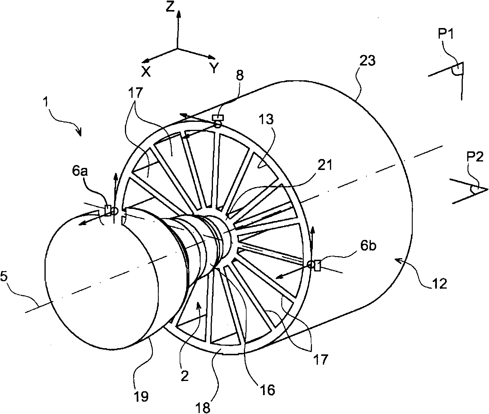
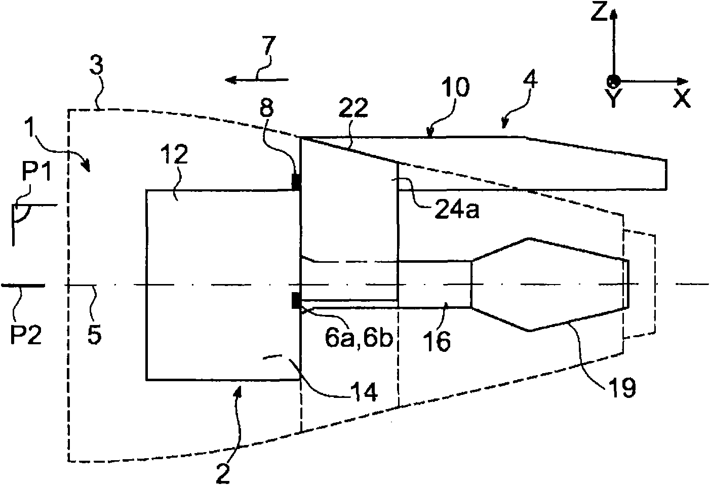
[0054] refer to image 3 , there can be seen an engine assembly 1 for an aircraft according to a preferred embodiment of the present invention, which assembly 1 is fixed under an aircraft wing (not shown).

[0055] Overall, the engine assembly 1 is also referred to as an integrated propulsion system, which consists of a turbojet engine 2, a nacelle 3 (shown in dashed lines for clarity), and suspension means for suspending the turbojet engine on a suspension frame 4, which The device preferably consists of a plurality of engine fasteners 6a, 6b, 8 which are fixedly connected to the rigid structure 10 of the hanger (here image 3 , the fastener 6b is covered by the fastener 6a). As an illustration, it should be noted that the assembly 1 includes a further set of fasteners (not shown) for securing the suspension of the assembly 1 under the wing of the aircraft.

[0056] Throughout the following description, by convention, X is referred to as the longitudinal direction of the su...


PUM


Abstract

The invention relates to an aircraft engine assembly comprising an annular load-transfer structure surrounding the central casing (16) and connected to a plurality of substantially planar structures arranged externally with respect to this annular structure, and acting upon it at a plurality of load application points (68a, 68b, 68c). According to the invention, at least one connecting link is associated with each of the load application points, the said link being positioned tangentially with respect to the casing (16) and having an inner end (62a) connected to this casing and an outer end (62b) connected to the structure (60) so that it has passing through it an imaginary plane (66a, 66b, 66c) in which said structure is located and which passes through the load application point.

Description

technical field [0001] The present invention generally relates to an engine assembly for an aircraft comprising a turbojet engine, a nacelle surrounding the turbojet engine, and a hanger provided with a rigid structure and a plurality of engine fasteners arranged in Between the rigid structure of the suspension frame and the turbojet engine. Background technique [0002] The suspension mount, also known as EMS ("Engine Mounting Structure"), allows the suspension of the turbojet engine under the wing of the aircraft, or the installation of the turbojet engine on the wing, or the installation of the turbojet engine in the fuselage rear. In fact, this hanger is designed to constitute a connection interface between the turbojet engine and a given structural part of the aircraft. This suspension mount allows the transmission of the forces generated by the associated turbojet engine to the structure of the aircraft and also allows the arrangement of fuel passages, electrical, hy...

Claims


Application Information

Patent Timeline
Patent Type & Authority Applications(China)
IPC IPC(8): B64D27/26F02C7/20
CPCY02T50/672F02C7/20B64D2027/266B64D27/26Y02T50/60
Inventor 弗雷德里克·茹尔纳德德尔菲娜·雅尔贝
Owner AIRBUS OPERATIONS (SAS)
Why Eureka
Try Eureka