Adjustable designed model
An adjustable and modelling technology, applied in the field of mannequins, can solve the problem of single body shape, and achieve the effect of body shape standard, reasonable structure design and simple adjustment.
- Summary
- Abstract
- Description
- Claims
- Application Information
AI Technical Summary
Problems solved by technology
Method used
Image

Examples
Embodiment Construction
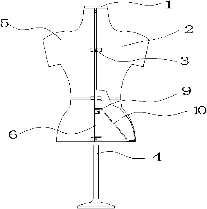
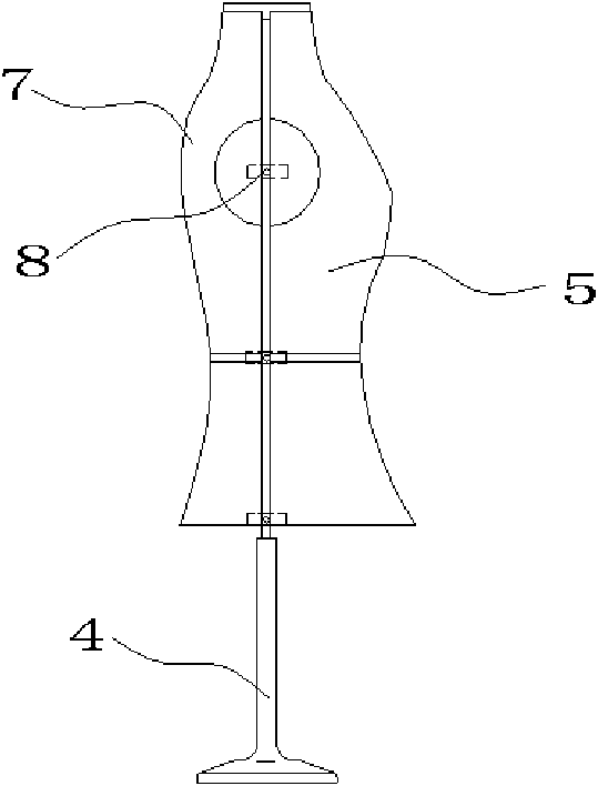
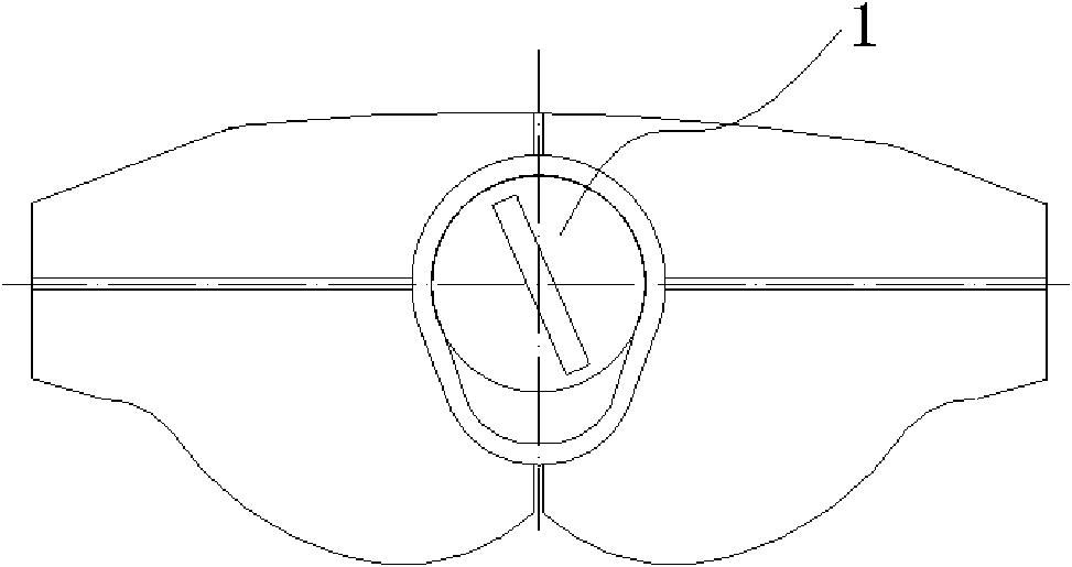
[0029] The technical solutions of the present invention will be further specifically described below through the embodiments and in conjunction with the accompanying drawings.
[0030] see figure 1 and figure 2, the present embodiment comprises a support 4, a human body model, and we divide the human body model into 4 parts, namely the right front phantom 2, the left front phantom 5, the left rear phantom 7 and the right rear phantom, and the top of the phantom is set A disc-type adjustment lock 1, 4 pieces of linear adjustment locks 3 for the chest, waist, and lower part of the phantom, the junction of the right front phantom 2 and the arm end of the right rear phantom, the left front phantom 5 and the left rear phantom A side adjustment lock 8 is established at the arm end junction of 7. Side adjustment lock 8 and linear adjustment lock 3 structures can be set to be identical, and upper tooth push rod 33 and lower tooth push rod 36 on it are respectively fixed with adjace...
PUM
 Abstract
Description
Claims
Application Information
PatSnap Eureka turns technology decisions into work you can execute. Powered by our Innovation Knowledge Graph, it runs expert workflows across engineering, life sciences, materials and intellectual property. Get your review-ready output in minutes.


