Dust barrel with double dust compressing function

A technology of dust bucket and function, applied in the field of dust bucket, can solve the problem of low dust compression efficiency and achieve the effect of improving compression efficiency

Inactive Publication Date: 2011-02-02
LG ELECTRONICS (TIANJIN) APPLIANCES CO LTD
View PDF0 Cites 13 Cited by
  • Summary
  • Abstract
  • Description
  • Claims
  • Application Information

AI Technical Summary

Problems solved by technology

When the inhaled dust continues to increase, the rotation angle of the compression plate will become smaller and

Method used


Image

  • Dust barrel with double dust compressing function
  • Dust barrel with double dust compressing function
  • Dust barrel with double dust compressing function

Examples


Embodiment Construction

[0026] Below in conjunction with accompanying drawing and specific embodiment the present invention is described in further detail:

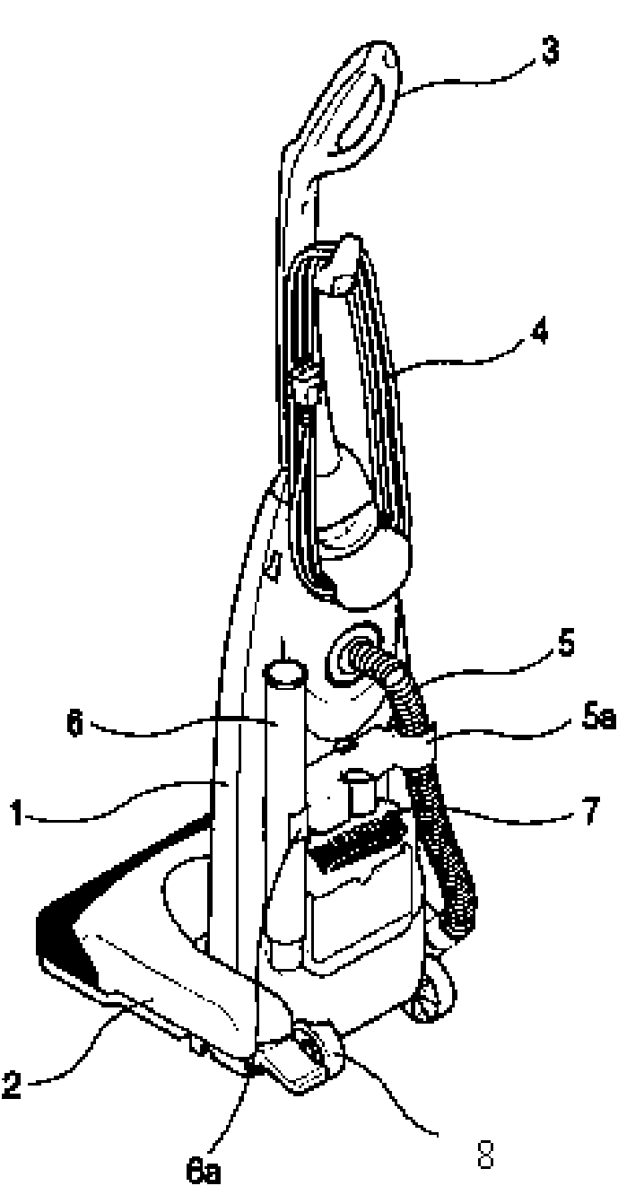
[0027] The working principle of the vacuum cleaner of the present invention is the same as that of the prior art, and the prior art can be referred to, so it will not be described again, and the same symbols as those of the prior art will be used. The differences between the present invention and the prior art will be described below Detailed explanation:

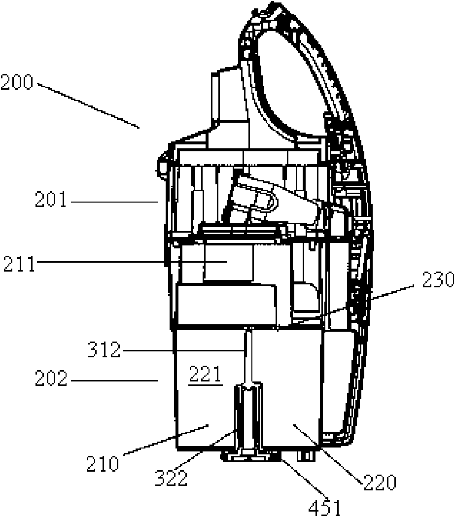
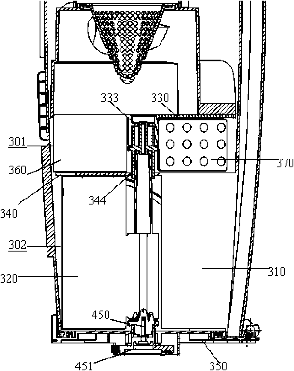
[0028] Such as image 3 As shown in FIG. 6 , the partition plate 340 horizontally fixed in the middle of the dust bucket divides the dust bucket 202 into two parts: the area between the upper partition plate 330 and the partition plate 340 is the upper compression chamber 341, which is hinged in the collection The area between the bottom cover 350 and the partition plate 340 on the dust bucket housing is the lower compression chamber 342 .

[0029] A circular through hole 344 is disposed in...


PUM

PropertyMeasurementUnit
Angleaaaaaaaaaa

Abstract

The invention discloses a dust barrel with a double dust compressing function, comprising compression cavities and a bottom cover, wherein the center of the bottom cover is provided with a driven gear wheel and a connecting head, a partition plate is arranged in the dust barrel and used for dividing the dust barrel into an upper-layer compression cavity and a lower-layer compression cavity, an upper movable compression plate and an upper fixed compression plate are arranged in the upper-layer compression cavity, the upper movable compression plate is rotatablely fixed on the upper partition plate, and the upper fixed compression plate is fixedly connected with the upper partition plate; a lower movable compression plate and a lower fixed compression plate are arranged in the lower-layer compression cavity, the upper end of a rotating shaft of the lower movable compression plate is fixedly connected with a rotating shaft of the upper movable compression plate, the lower end of the rotating shaft is engaged with the connecting head, and the lower fixed compression plate is fixedly connected with the partition plate. The dust barrel realizes twice compression of dust and improves compression efficiency.

Description

technical field [0001] The invention relates to a vacuum cleaner, in particular to a dust bucket with dust compression function. Background technique [0002] In general, a vacuum cleaner is a device for sanitation that uses vacuum pressure generated by a vacuum motor installed in its body to suck dust-containing gas and then filters the dust in the gas. [0003] figure 1 It is a three-dimensional schematic diagram of a vacuum cleaner in the prior art. Such as figure 1 As shown, the vacuum cleaner includes a vacuum cleaner body 1 with a suction force generator therein, a dust collector for separating dust from the introduced air and storing the separated dust; The suction nozzle 9 passed through; and the electric wire 4 for power supply; the handle 3 and the roller 8 that allow the user to operate the vacuum cleaner; the connecting hose 5 that connects the suction nozzle 9 to the vacuum cleaner body 1, and the hose 5 fixed part 5a. One side of the main body 1 is fixed w...

Claims


Application Information

Patent Timeline
IPC IPC(8): A47L9/16
Inventor 高岩
Owner LG ELECTRONICS (TIANJIN) APPLIANCES CO LTD
Why Eureka
Try Eureka