Moving mechanism of automatic steel bar bender

A technology of moving mechanism and bending machine, which is applied in the field of moving mechanism, can solve the problems such as the inability to automatically adjust the gap between the gear and the rack, the bumpy running of the automatic steel bar bending machine, and the difficulty in ensuring the straightness of the rack, etc., to achieve light weight, low cost, The effect of simple structure

Active Publication Date: 2011-02-02
TJK MACHINERY TIANJIN
View PDF7 Cites 9 Cited by
  • Summary
  • Abstract
  • Description
  • Claims
  • Application Information

AI Technical Summary

Problems solved by technology

The meshing of the gear and the rack is a rigid connection, and the gap between the gear and the rack cannot be automatically adjusted
[0005] 2. The track in the prior art is long, and the rack on the track is welded in sections. It is difficult to ensure the straightness of the welded rack, and hard friction will occur between the rack and the gear, which will cause the automatic steel bar bending machine to walk Bumps, resulting in poor quality of bent steel bars

Method used


Image

  • Moving mechanism of automatic steel bar bender
  • Moving mechanism of automatic steel bar bender
  • Moving mechanism of automatic steel bar bender

Examples


Embodiment Construction

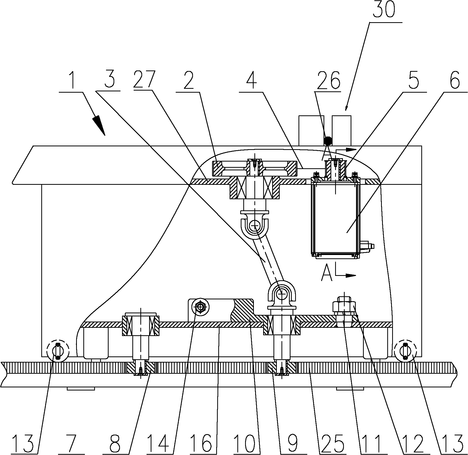
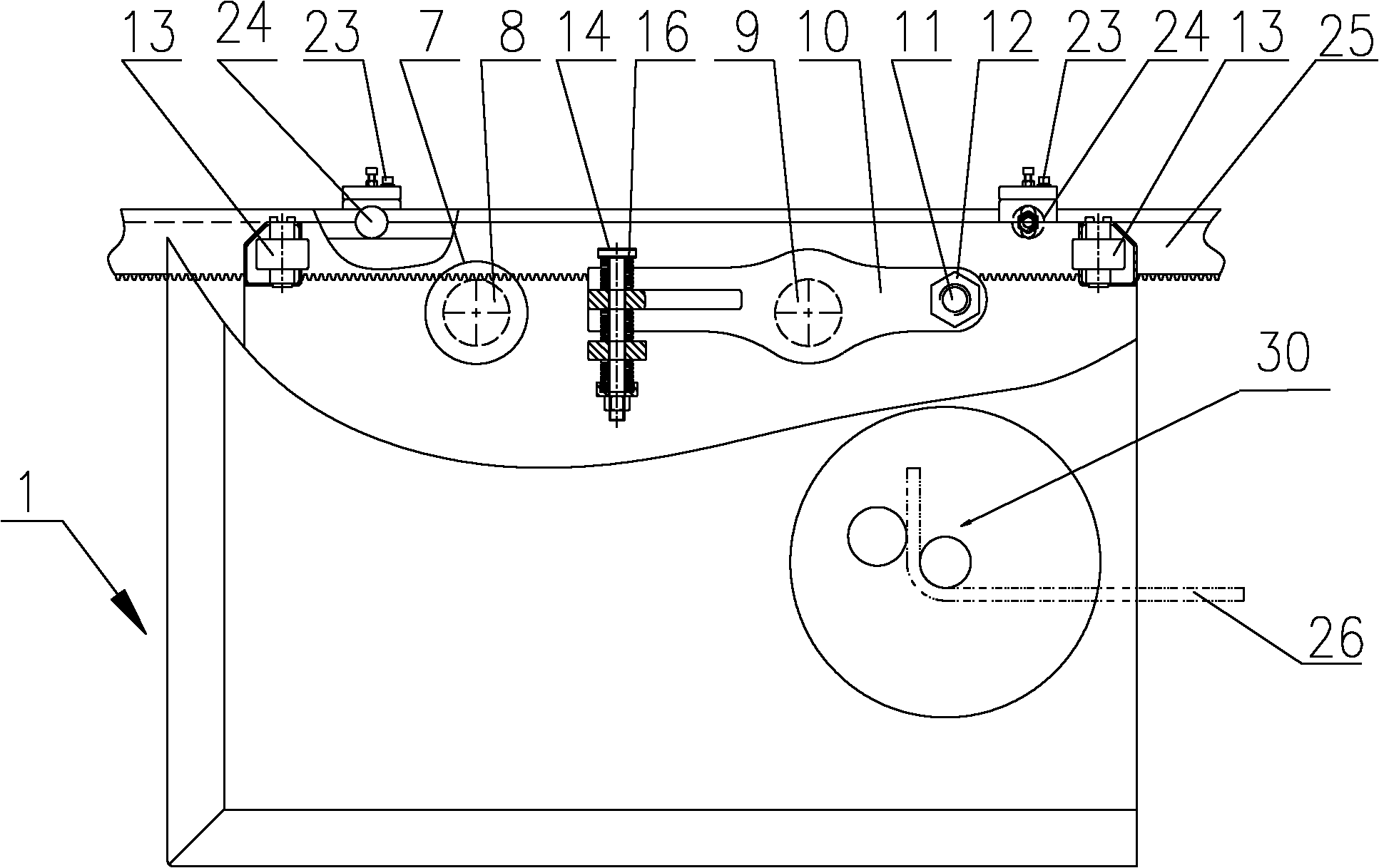
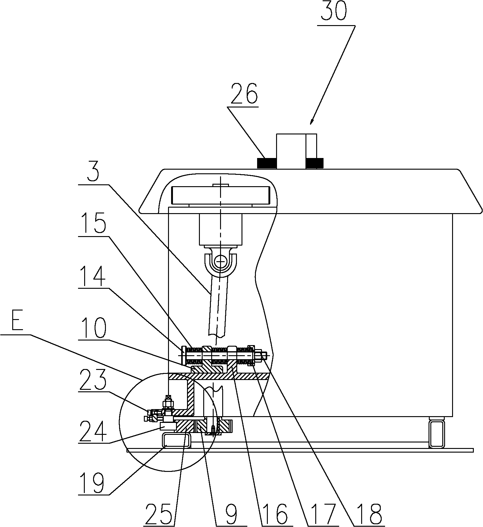
[0016] figure 1 It is a front view with a partial section of the present invention; figure 2 yes figure 1 Top view with partial section in ; image 3 yes figure 1 Left side view with breakout in ; Figure 4 yes figure 1 Middle A-A sectional view; Figure 5 yes image 3 Enlarged view of middle A and E.

[0017] As shown in the figure, the present invention provides a moving mechanism of a steel bar automatic bending machine, the moving mechanism includes: a track rack 25; a bending machine box 1 that moves along the track rack 25; The driving gear 9 meshed with the rack 25, the driving mechanism for driving the driving gear 9 to rotate includes: the driving gear 9 is connected to one end of the universal coupling 3, and the other end of the universal coupling 3 is connected to the output of the conveyor belt transmission mechanism. The input end of the conveyor belt transmission mechanism is connected to the power drive unit 6.

[0018] The shaft at one end of the uni...


PUM


Abstract

The invention discloses a moving mechanism of an automatic steel bar bender, which comprises a rail rack, a bender box moving along the rail rack, a driving gear arranged on the inner side of the bender box and engaged with the rail rack and a travel driving mechanism for driving the driving gear to rotate, wherein the driving gear is connected with one end of a universal coupling, the other end of the universal coupling is connected with the output end of a conveyer belt transmission mechanism, and the input end of the conveyer belt transmission mechanism is connected with a power driving unit. The invention has the beneficial effects of overcoming defects of the prior art, using the universal coupling and the conveyer belt transmission mechanism as moving mechanisms and has the advantages of light weight, low cost, simple structure, convenient maintenance, stable working, energy consumption saving, and the like in comparison with the prior art. A buffering mechanism is used for avoiding hard friction between the rack and the gear and overcoming the travel bumping of the automatic steel bar bender, and thus, the bent steel bar has good quality.

Description

technical field [0001] The invention relates to an automatic steel bar bending machine, in particular to a moving mechanism of the steel bar automatic bending machine. Background technique [0002] The structure of the steel bar automatic bending machine includes: the bending head part and the track on which the bending head part moves. The bending head part includes: a box body, in which there are: a bending head, a motor, and a reduction box; the input end of the reducer is connected to the motor, the output end of the reducer is connected to the gear, the gear meshes with the rack, and the rack is fixed On the track, the gear turns to realize the movement of the curved head part on the track. The bending head bends the fixed steel bar during the movement. [0003] There is following shortcoming in above-mentioned prior art steel bar automatic bending machine: [0004] 1. The weight of the bending machine head in the prior art is large, and the inertia of moving on the ...

Claims


Application Information

Patent Timeline
Patent Type & Authority Applications(China)
IPC IPC(8): B21F1/00
Inventor 陈振东
Owner TJK MACHINERY TIANJIN
Why Eureka
Try Eureka