Internal spherical gear and external spherical gear

A technology of inner spherical surface and outer spherical surface, applied in the direction of gear transmission, belt/chain/gear, components with teeth, etc., can solve the problems of large starting and running load, insufficient strength of teeth, inconvenient heat treatment and quenching, etc. The effect of increasing torque and saving manufacturing costs

Pending Publication Date: 2017-09-01
李仁元
View PDF5 Cites 0 Cited by
  • Summary
  • Abstract
  • Description
  • Claims
  • Application Information

AI Technical Summary

Problems solved by technology

[0002] At present, the domestic tanning machinery (drum) equipment uses medium-sized and large-scale spur gear transmission, and the large-scale production equipment (drum) of tanning machinery has a maximum loading capacity of more than 80 tons of fur (including chemical raw material aqueous solution). 1. The rotational transmission torque of the passive spur gear is small, and the active and passive spur gears increase the torque, but because the passive large spur gear of the existing drum body is installed on the outer end surface of the drum body (disc skeleton), it is larger than the diameter of the passive larg...

Method used


Image

  • Internal spherical gear and external spherical gear
  • Internal spherical gear and external spherical gear
  • Internal spherical gear and external spherical gear

Examples


Embodiment Construction

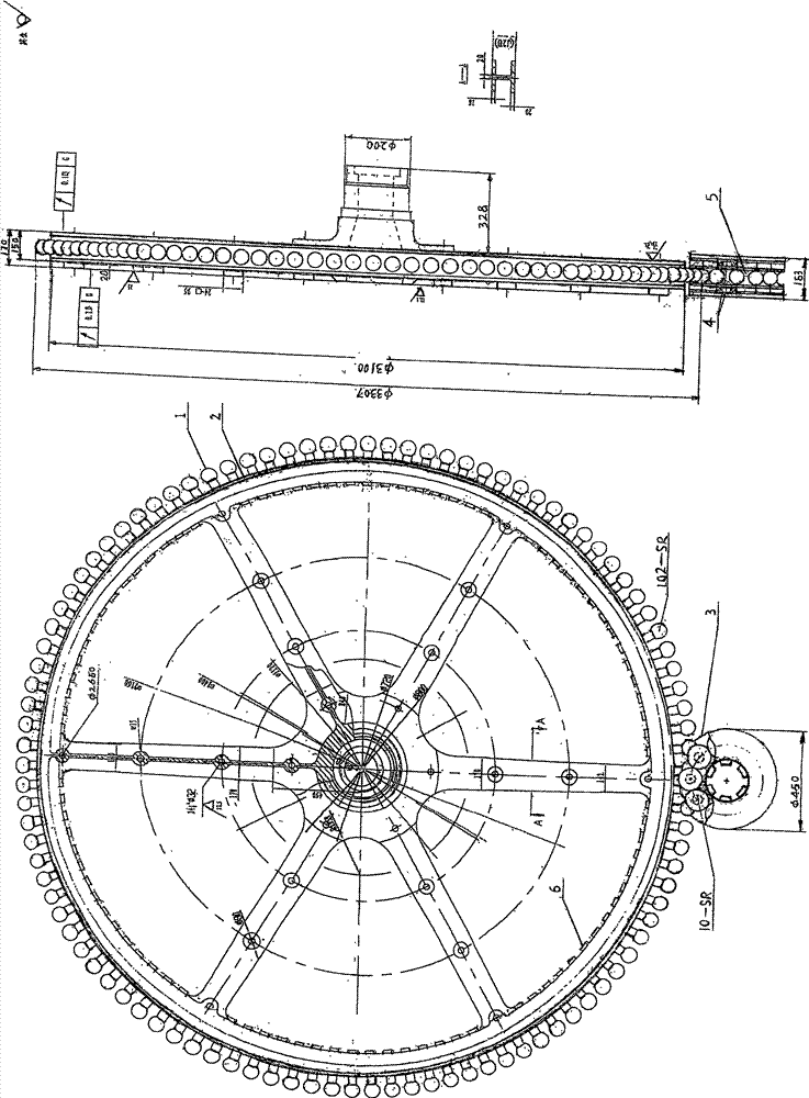
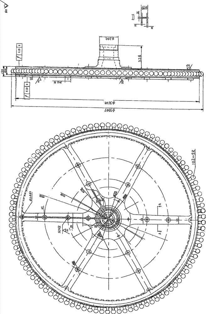
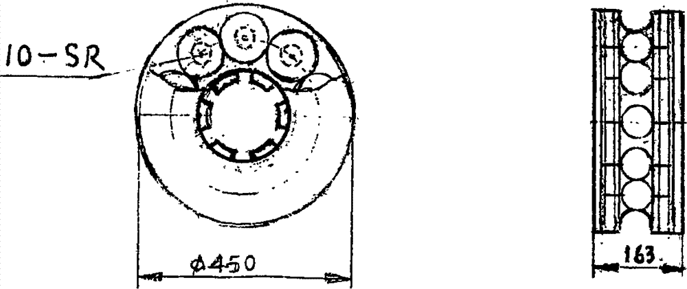
[0022] this invention figure 1 , Figure 4 , Figure 7 The optimization of the inner spherical gear and the outer spherical gear lies in: using the principle of spherical lines, adopting spherical tooth shape and high-frequency quenching, it can form a heavy-duty rotary transmission rigidity that cannot be easily obtained by traditional spur gear transmission methods. The spherical gear 5 twists the outer spherical gear 1 to rotate, and the outer spherical gear 1 drives the inner spherical gear 5 (under the action of the bearing) to slide in the same direction, which solves the hard friction and easy wear between the inner spherical gear 5 and the outer spherical gear 1 , the production and use time is long, the inner spherical gear 5 and the outer spherical gear 1 can be disassembled and replaced, and the new inner spherical gear 5 and outer spherical gear 1 can be replaced. The large and small gear ring seats 2 and 3 should not be replaced. The waste of energy greatly save...


PUM

PropertyMeasurementUnit
Diameteraaaaaaaaaa

Abstract

The invention discloses an internal spherical gear and an external spherical gear in the figure 1, and relates to high load of a tanning drum, low torque of a spur gear, high starting load and damaged gear shape. An internal spherical tooth consists of a horizontal shaft middle peripheral internal R semiarc and two end surface bearing holes. An external spherical tooth consists of a fan ring large arc middle connected vertical shaft cylinder lower end surface and a vertical shaft cylinder upper end surface connected circular ball. Two shaft shoulders are matched with two end surface bearing holes, a gear ring base shaft hole and the horizontal shaft middle peripheral internal R semiarc to combine as an internal spherical line. A fan ring parallel surface is matched with a large gear ring base groove and a section to combine as a fan ring arch circle. A large gear base in the figure 1 replaces a drum disc skeleton to increase the torque of the external spherical gear to solve low torque of the spur gear, high starting load and damaged gear shape. The external spherical tooth drives the internal spherical tooth to slide and rotate in the same direction to solve hard friction and easy wear between teeth, and long service life. The internal and external spherical teeth are replaced, and large and small gear ring bases are not replaced to save the production cost. The internal and external spherical gears are applied to rotary transmission of tanning machinery.

Description

technical field [0001] The inner spherical gear and the outer spherical gear of the present invention relate to the transmission usage of domestic tanning machinery (drum) equipment spur gears, and summarize the practical defects of the use of medium-sized and large spur gears in tanning machinery, and develop and design the inventive inner spherical gear, Outer spherical gears, inner spherical gears, and outer spherical gears are applicable to the rotation transmission of medium-sized and large-scale (drum) equipment in tanning machinery, and are also applicable to the rotation transmission of cement machinery and mining machinery equipment. Claims for protection of the invention figure 1 , Figure 4 , Figure 7 The technical scheme of inner spherical gear and outer spherical gear with shape and structure. Background technique [0002] At present, the domestic tanning machinery (drum) equipment uses medium-sized and large-scale spur gear transmission, and the large-scale ...

Claims


Application Information

Patent Timeline
IPC IPC(8): F16H55/17F16H1/06
CPCF16H1/06F16H55/17
Inventor 李仁元
Owner 李仁元
Why Eureka
Try Eureka