Tooth row positioning device and working method thereof

A technology of positioning device and tooth row, which is applied in printing, printing presses, general parts of printing machinery, etc., can solve the problems that the adjustment device can not completely solve, affect the accuracy of the equipment, and reduce the accuracy of the equipment, so as to improve the chain stretching problem, The effect of reducing maintenance and installation costs and reducing space occupation

Active Publication Date: 2011-02-02
MASTERWORK GROUP CO LTD
View PDF9 Cites 10 Cited by
  • Summary
  • Abstract
  • Description
  • Claims
  • Application Information

AI Technical Summary

Problems solved by technology

In the post-press equipment that can complete the die-cutting, bronzing or stripping processes in one pass, the paper is driven by chains to hold multiple groups of teeth in a closed loop trajectory, and then passes through bronzing, die-cutting, stripping and stripping in sequence. In the delivery station, due to the long closed chain, the accumulated micro-stretch of each chain link will increase the stretch of the entire chain during long-term use, which will affect the accuracy of the equipment
In the existing products, when the chain is slightly stretched, it can be temporarily solved by the adjustment device, but with the accumulation of equipment usage time, the chain stretching phenomenon becomes more and more obvious, resulting in a decrease in equipment accuracy, frequent shutdown adjustments, and reduced work efficiency , the adjustment device cannot completely solve the problem of chain stretching, only by replacing the entire closed chain, but the process is very cumbersome and consumes a lot of manpower and material resources

Method used


Image

  • Tooth row positioning device and working method thereof
  • Tooth row positioning device and working method thereof
  • Tooth row positioning device and working method thereof

Examples


Embodiment

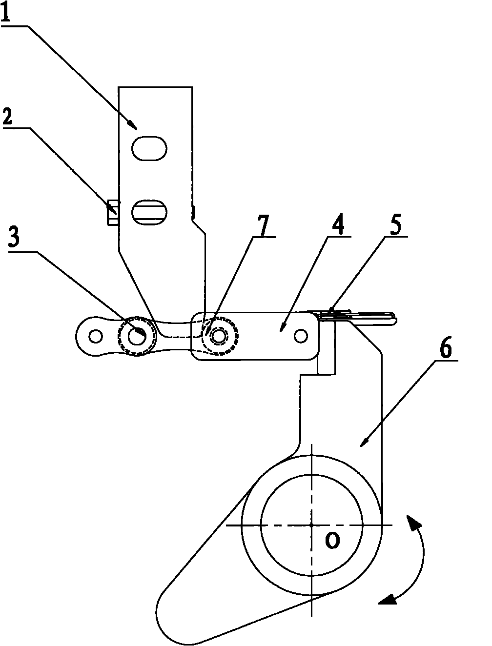
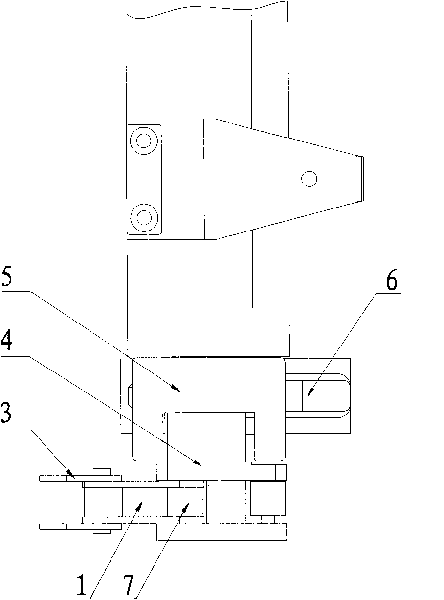
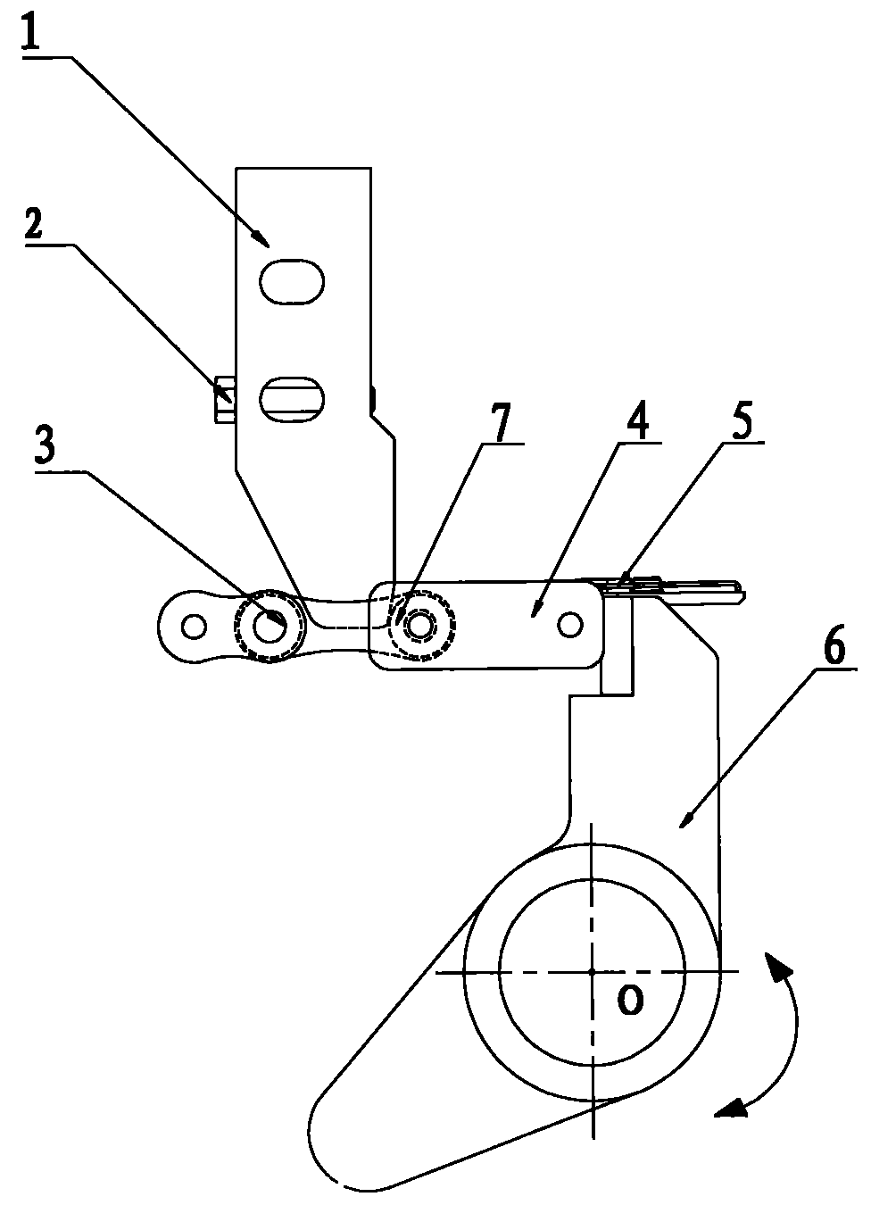
[0019] Embodiment: a kind of row of teeth positioning device (see figure 1 , figure 2 ), is characterized in that it is made of chain positioning block 1, adjusting screw 2, chain 3, connecting block 4, tooth row body 5, rear positioning swing bar 6 and positioning roller 7; said chain positioning block 1, adjusting screw 2. The chain 3, the connecting block 4, the rear positioning swing bar 6 and the positioning roller 7 are all symmetrically installed on both sides of the tooth row body 5; the said connecting block 4 is connected to the chain 3; the said chain positioning block 1 is located on the Directly above the chain link of the chain 3 connected to the connecting block 4, the chain positioning block 1 is fixed on the fixture; the said positioning roller 7 is a roller on the connecting block 4 chain link; the said tooth row body 5 The two ends are respectively fixedly connected on the connection block 4; the said back positioning swing link 6 is a symmetrical part, an...


PUM


Abstract

The invention discloses a tooth row positioning device. The device is characterized by comprising a chain positioning block, an adjusting screw, a chain, a connecting block, a tooth row body, a post-positioning swing rod, and a positioning roller, wherein the connecting block is connected with the chain; the chain positioning block is fixed on a fixing part; the positioning roller is a roller on a chain link of the connecting block; the two ends of the tooth row body are fixedly connected on the connecting block respectively; the post-positioning swinging rod is a symmetric part; and the adjusting screw is arranged on the chain positioning block. A working method comprises the following steps of: positioning the tooth row body at a processing position; rotating the post-positioning swinging rod counterclockwise; lifting the tooth row body and the connecting body; after finishing positioning, starting processing paper; after finishing processing, rotating the post-positioning swing rodclockwise; descending the tooth row body and the connecting block; and after separating completely, positioning the tooth row body to a next position. The device has the following advantages: solution of the problem of chain stretching of equipment after printing, improvement on the precision stability of the equipment after printing, simple structure, reduction of space occupation, reduction of maintenance installation cost and improvement on work efficiency.

Description

(1) Technical field: [0001] The invention is suitable for printing machinery, especially a tooth row positioning device and working method suitable for post-press equipment. (two) background technology: [0002] Today, with the rapid development of printing equipment, high precision, high speed, and high stability have always been important indicators for printing manufacturers to judge whether printing equipment is good or not. In the post-press equipment that can complete the die-cutting, bronzing or stripping processes in one pass, the paper is driven by chains to hold multiple groups of teeth in a closed loop trajectory, and then passes through bronzing, die-cutting, stripping and stripping in sequence. In the delivery station, due to the long closed chain, the accumulated micro-stretch of each chain link will increase the stretch of the entire chain during long-term use, which will affect the accuracy of the equipment. In the existing products, when the chain is slight...

Claims


Application Information

Patent Timeline
Patent Type & Authority Applications(China)
IPC IPC(8): B41F21/08
Inventor 韦树远彭章波
Owner MASTERWORK GROUP CO LTD
Why Eureka
Try Eureka