Drainage system for overhead bridge

A technology for drainage systems and viaducts, applied in bridges, bridge parts, bridge construction, etc., can solve the problems of blockage of debris in drainage pipes, inconvenient maintenance and dredging, and less collection, to avoid potential safety hazards and increase the effect of aesthetics.

Active Publication Date: 2012-10-31
SHANGHAI URBAN CONSTR DESIGN RES INST GRP CO LTD
View PDF7 Cites 0 Cited by
  • Summary
  • Abstract
  • Description
  • Claims
  • Application Information

AI Technical Summary

Problems solved by technology

[0002]The bridge deck drainage structure of traditional viaducts usually adopts a system of bridge deck water collection wells, drainage pipes, and ground collection wells. It is installed at the abutment, so that there are fewer rainwater collection points on the bridge deck, and the collection amount is less. Moreover, the diameter of the drainage pipe is small, and the drainage pipe is easily blocked by large debris, which is inconvenient for maintenance and dredging; in addition, the drainage Pipes are generally hung on the outside of the bridge pier structure, which is not only visually unsightly, but also in some special areas with high safety requirements, such as the section crossing the high-speed rail, due to the particularity of the crossing area, the installation of external drainage pipes may cause aging and falling off of the pipes. , blocking and causing safety hazards

Method used


Image

  • Drainage system for overhead bridge
  • Drainage system for overhead bridge

Examples


Embodiment Construction

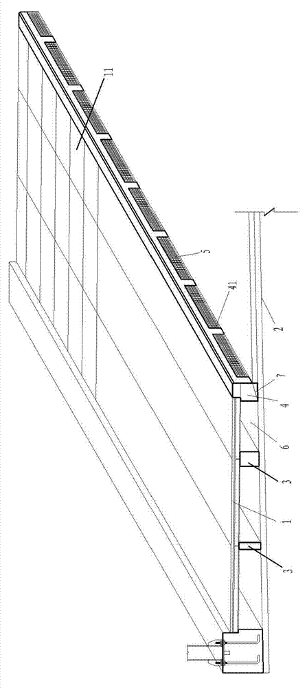
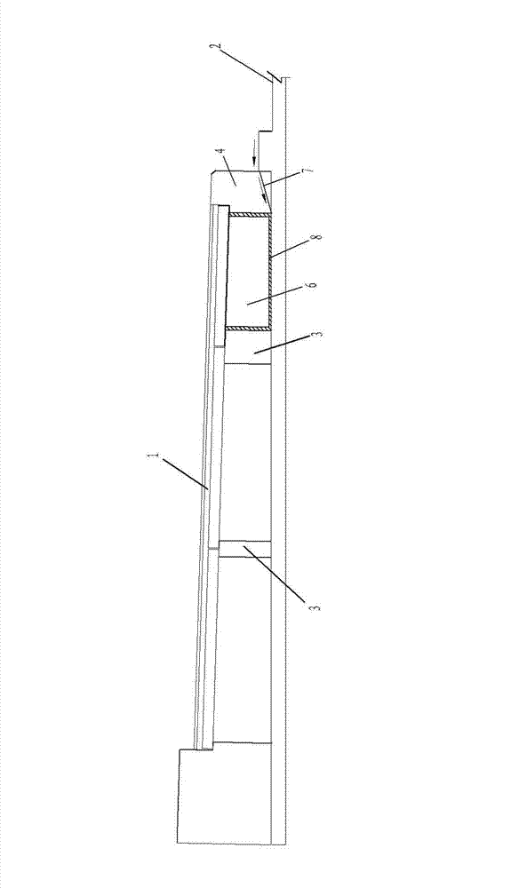
[0020] figure 1 with figure 2 A preferred embodiment of the viaduct drainage system of the present invention is shown. The viaduct includes a sidewalk 1 , a carriageway 2 and a side stone 4 between the sidewalk 1 and the carriageway 2 . The side stone 4 is provided with a through hole 41 for rainwater to flow in, and a water collection and drainage channel 6 extending longitudinally along the sidewalk 1 is provided below the sidewalk 1 . In a specific embodiment, the bottom surface of the through hole 41 on the side stone 4 is set as a diversion slope 7 inclined towards the water collection and drainage channel 6, so as to facilitate the rainwater flowing into the through hole 41 to quickly flow to the water collection and drainage channel 6 . In a specific embodiment, a water inlet grill 5 is arranged in the through hole 41 of the side stone 4 to prevent garbage and sundries from entering the water collection and drainage channel 6 .

[0021] Pad beams 3 are arrang...


PUM


Abstract

The invention discloses a drainage system for an overhead bridge which comprises a running lane, a side pavement and curbstone arranged between the running lane and the side pavement, wherein the curbstone is provided with a through hole in which rainwater flows, a water collecting and draining channel extending along the longitudinal direction is arranged below the side pavement, and the water collecting and draining channel is connected with the through hole on the curbstone. The drainage system has the advantages of large water collecting and draining quantity, difficult blockage of drained water and high safety.

Description

technical field [0001] The invention relates to a bridge deck drainage structure, in particular to a viaduct drainage system. Background technique [0002] The bridge deck drainage structure of traditional viaducts usually adopts a system of bridge deck water collection wells, drainage pipes, and ground collection wells. Water collection wells and drainage pipes are generally only installed at bridge piers and abutments, so that there are fewer bridge deck collection points for rainwater. , the amount of collection is less, and the diameter of the drainage pipe is small, the drainage pipe is easily blocked by larger debris, and maintenance and dredging are inconvenient; in addition, the drainage pipe is generally hung outside the pier structure, which is not only visually unsightly , In some special areas with high safety requirements, such as the section across the high-speed rail, due to the particularity of the crossing area, the installation of external drainage pipes ma...

Claims


Application Information

Patent Timeline
Patent Type & Authority Patents(China)
IPC IPC(8): E01D19/08
Inventor 吴刚陈剑明沙丽新刘晓萍黄锦源刘佳朱鹏志聂志宏周晓君
Owner SHANGHAI URBAN CONSTR DESIGN RES INST GRP CO LTD
Why Eureka
Try Eureka