Flushing arrangement for a WC and method of operating such a flushing arrangement

A flushing device and pulse technology, applied in water supply devices, flushing toilets, buildings, etc., can solve problems such as the reduction of the acceleration effect of jet nozzles

Inactive Publication Date: 2011-02-02
GEBERIT INT AG
View PDF10 Cites 2 Cited by
  • Summary
  • Abstract
  • Description
  • Claims
  • Application Information

AI Technical Summary

Problems solved by technology

[0004] Tests have shown that the acceleration effect of jet no

Method used


Image

  • Flushing arrangement for a WC and method of operating such a flushing arrangement
  • Flushing arrangement for a WC and method of operating such a flushing arrangement
  • Flushing arrangement for a WC and method of operating such a flushing arrangement

Examples


Embodiment Construction

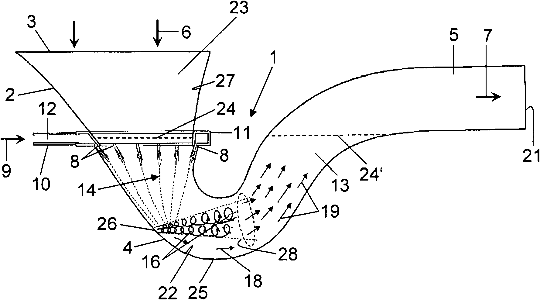
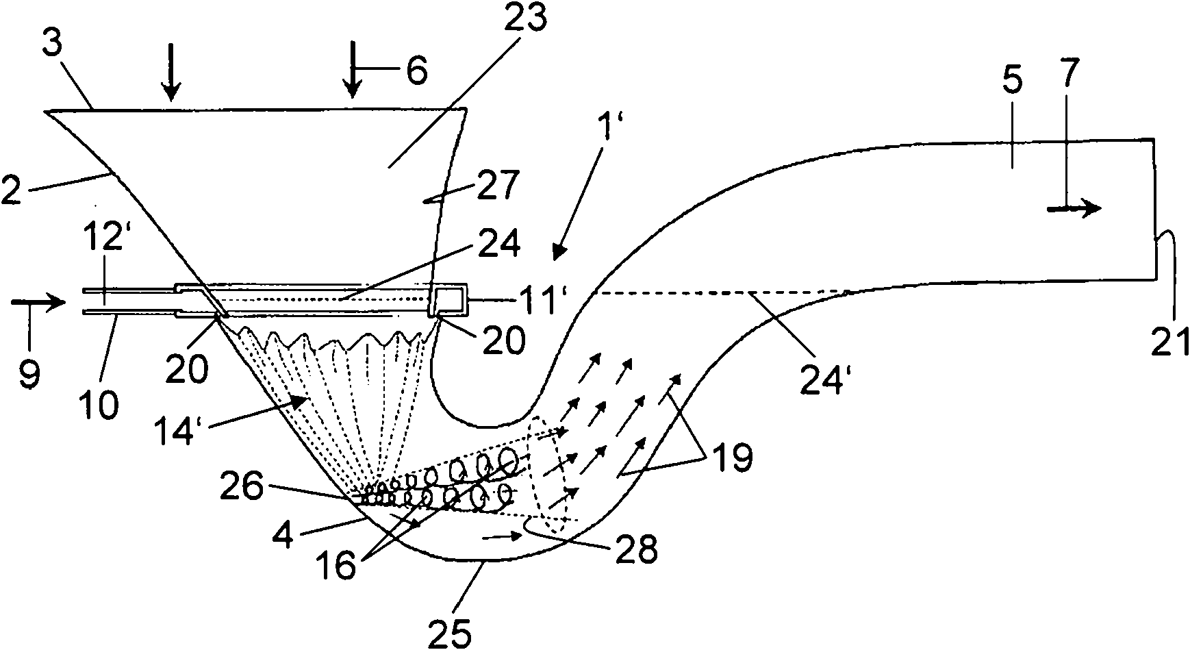
[0018] figure 1 The flushing device 1 shown in has a toilet bowl 2 with an inlet 3 and an outlet 21 . In the domain of the inlet 3 there is a flushing channel (not shown here), known per se, from which water flows during the main flushing along the interior 27 in the direction of arrow 6 downwards to In the U-shaped bending part 4.

[0019] The water 13 located in the U-bend 4 exits from the U-bend 4, leaves the toilet bowl 2 at an outlet 21, and passes from there into a downpipe (not shown here). The toilet bowl 2 therefore has a lowering region which extends as far as the apex 25 of the U-shaped bend 4 . Then start ascending the area. The water 13 forms a U-bend water line 24 in the descending area and a U-bend water line 24' in the ascending area. Of course, the U-bend water lines 24 and 24' are in the same horizontal plane. The water for the main flush originates, for example, from a water reservoir (not shown here) or directly from the water mains.

[0020] The devi...


PUM


Abstract

The invention discloses a flushing arrangement for a WC. The flushing arrangement (1) has a toilet bowl (2) with an inlet (3) and an outlet (18). A pulse generating unit (8,20) is arranged between the inlet and the outlet in a U-bend (4). The pulse generating unit accelerates water, present in the U-bend and forming an air trap, for flushing operation in the direction of the outlet. The pulse generating unit (8,20) is arranged in the downward range of the toilet bowl (2) and generates the downward poppets (14,14') in the flushing process. The flow downwards narrows and a wall jet (28) is formed at a saddle point (26) and especially thoroughly cleans the U-bend (4). The invention also discloses a method of operating the flushing arrangement.

Description

technical field [0001] The invention relates to a flushing device for a WC having a toilet bowl with an inlet and an outlet and between them means for generating pulses, present in a U-shaped bend and forming an anti-odor trap Water can be accelerated in the outlet direction by this pulse for flushing operation. Background technique [0002] According to the applicant's WO 95 / 04196, the consumption of flushing water is significantly reduced when the water present in the U-shaped bend is set in motion during the flushing process by so-called jet nozzles. Water discharged into the U-bend by the nozzle at a relatively high velocity may cause the water in the U-bend to accelerate towards the outlet, so the U-bend flushes out better. A disadvantage here is that the water flowing into the U-bend generates additional noise, and moreover, the action of the jet nozzle can be greatly reduced at least by solid matter in the U-bend. [0003] EP-A-1034338 discloses a WC which also has ...

Claims


Application Information

Patent Timeline
IPC IPC(8): E03D11/08
Inventor U·英格林A·厄恩格尔根P·施文德纳
Owner GEBERIT INT AG
Why Eureka
Try Eureka