Turbo compressor and refrigerator

A technology of turbo compressors and impellers, which can be used in compressors, compressors, irreversible cycle compressors, etc., and can solve troubles and other problems

Active Publication Date: 2011-02-02
DAIKIN IND LTD
View PDF12 Cites 7 Cited by
  • Summary
  • Abstract
  • Description
  • Claims
  • Application Information

AI Technical Summary

Problems solved by technology

Therefore, before restarting the operation of the compressor, it is necessary to discharge the condensed refrigerant liquid to the outside from the liquid discharge port or the like arranged below the scroll chamber, which becomes troublesome.

Method used


Image

  • Turbo compressor and refrigerator
  • Turbo compressor and refrigerator
  • Turbo compressor and refrigerator

Examples


Embodiment Construction

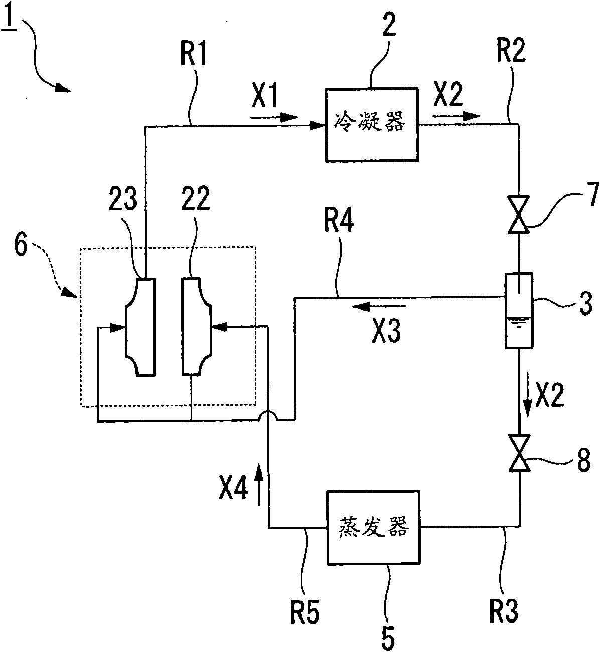
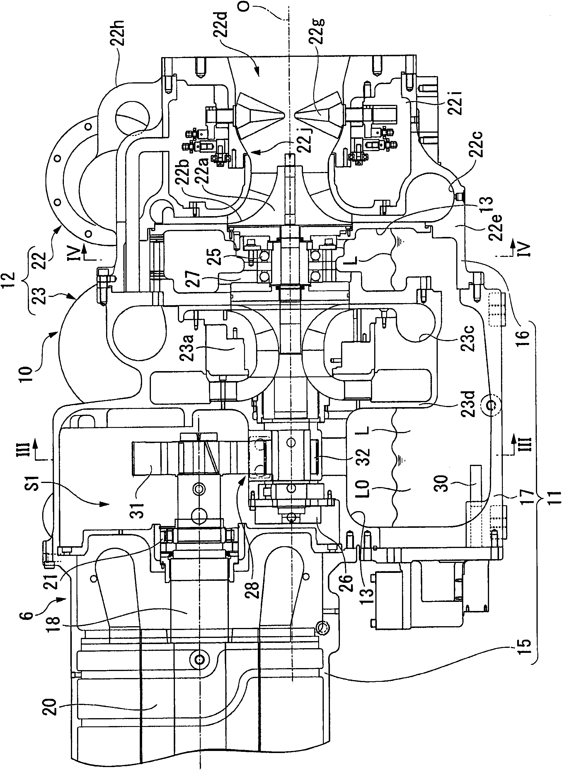
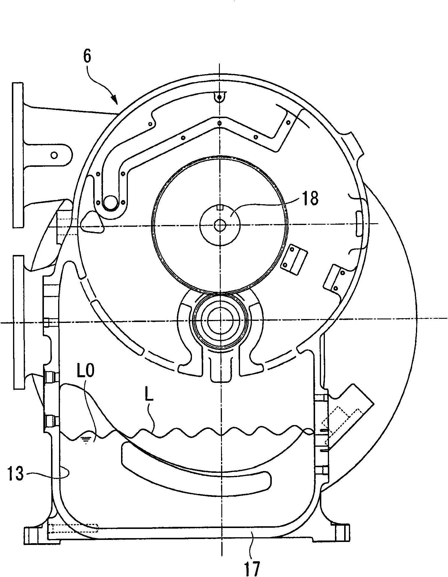
[0018] refer to Figure 1 to Figure 4 One embodiment of the turbo compressor and refrigerator according to the present invention will be described.

[0019] The turbo refrigerator (refrigerator) 1 according to this embodiment is installed in a building or a factory in order to generate, for example, cooling water for an air conditioner, such as figure 1 As shown, it is provided with a condenser 2 , an economizer 3 , an evaporator 5 and a turbo compressor 6 .

[0020] The condenser 2 is supplied with compressed refrigerant gas X1 that is a refrigerant (fluid) such as R134a compressed in a gaseous state, and cools and liquefies the compressed refrigerant gas X1 to become a refrigerant liquid X2. The condenser 2 as figure 1 As shown, the turbo compressor 6 is connected to the flow path R1 through which the compressed refrigerant gas X1 flows. In addition, the condenser 2 is connected to the economizer 3 via a flow path R2 through which the refrigerant liquid X2 flows. In the ...


PUM


Abstract

The invention provides a turbo compressor and a refrigerator. The turbo compressor includes an impeller; compression stages having scroll chambers which introduce the refrigerant to the impeller or lead the refrigerant compressed by the rotation of the impeller to the outside; and an oil tank in which a heater is disposed and an lubricant oil is stored, and at least a part of the scroll chambers is disposed in the vicinity of the oil tank.

Description

[0001] This application claims priority to Japanese Patent Application No. 2009-170191 for which it applied on July 21, 2009, and uses the content here. technical field [0002] The invention relates to a turbo compressor and a refrigerator. More specifically, it relates to a turbo compressor capable of compressing a fluid through a plurality of impellers, and a refrigerator including the turbo compressor. Background technique [0003] As a refrigerator that cools or freezes a cooling object such as water, a turbo refrigerator including a turbo compressor that compresses and discharges a refrigerant by a compression mechanism including an impeller or the like is known. In a compressor, as the compression ratio increases, the discharge temperature of the compressor increases and the volumetric efficiency decreases. Therefore, in a turbo compressor including a turbo refrigerator as described above, the refrigerant may be compressed in a plurality of stages (for example, refer...

Claims


Application Information

Patent Timeline
Patent Type & Authority Applications(China)
IPC IPC(8): F04D29/00
CPCF25B2400/01F25B31/002F04D29/063F25B1/053
Inventor 塚本稔小田兼太郎
Owner DAIKIN IND LTD
Why Eureka
Try Eureka