Simple gas-liquid separation apparatus in rotating development vacuum line

A gas-liquid separation device, vacuum pipeline technology, applied in separation methods, dispersed particle separation, chemical instruments and methods, etc., can solve problems such as mixing developer, and achieve the effects of reducing corrosion problems, simple structure, and rapid response

Active Publication Date: 2014-04-09
SHENYANG KINGSEMI CO LTD
View PDF6 Cites 3 Cited by
  • Summary
  • Abstract
  • Description
  • Claims
  • Application Information

AI Technical Summary

Problems solved by technology

[0003] In order to solve the existing problem of developer mixed in the vacuum pipeline when the substrate is positioned by vacuum adsorption for development, the purpose of the present invention is to provide a simple gas-liquid separation device in the vacuum pipeline for rotary development

Method used


Image

  • Simple gas-liquid separation apparatus in rotating development vacuum line
  • Simple gas-liquid separation apparatus in rotating development vacuum line

Examples


Embodiment Construction

[0016] The present invention will be described in further detail below in conjunction with the accompanying drawings.

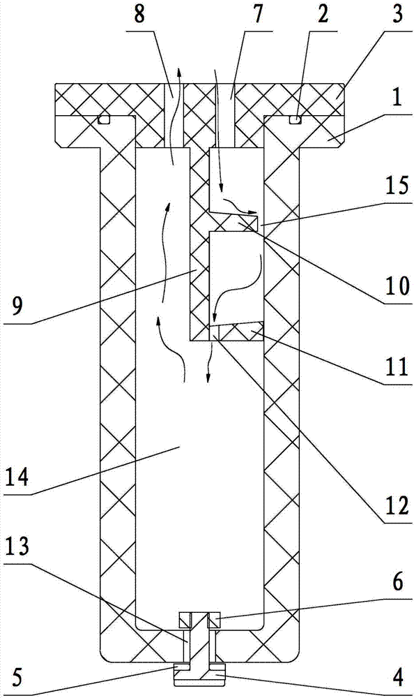
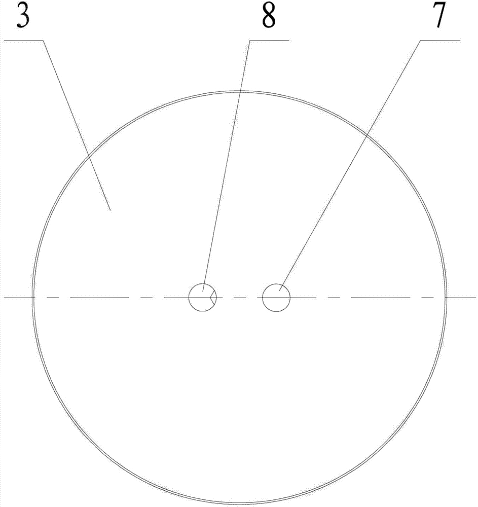
[0017] The present invention is used to remove the developing solution entering the vacuum pipeline during rotary development, such as figure 1 , figure 2 As shown, it includes a cylinder body 1, a cylinder cover 3 and a movable plug 4, wherein the cylinder body 1 is an internal hollow structure with a cavity 14 in the middle, one end of the cylinder body 1 is sealed and connected with the cylinder cover 3 through a sealing ring 2, and the other end is opened. There is a drain port 13.

[0018] The movable plug 4 is inserted in the liquid discharge port 13 , and the switch of the liquid discharge port 13 is controlled by the movable plug 4 reciprocating along the axial direction of the cylinder body 1 . The axial section of the movable plug 4 is an inverted "T" shape, and one end (the end with a smaller diameter) of the movable plug 4 is inserted into the ...


PUM


Abstract

The invention belongs to the field of rotating development of semiconductor industry photolithography technique basic steps, and specifically relates to a simple gas-liquid separation apparatus in a rotating development vacuum line. The simple gas-liquid separation apparatus comprises a barrel body, a barrel cover, and a movable plug; one end of the barrel body and the barrel cover are tightly connected, and the other end is provided with a liquid outlet; the moveable plug is inserted into the liquid outlet; opening and closing of the liquid outlet is controlled via reciprocating motion of the movable plug along axis of the barrel body; the barrel cover is provided with an air inlet and an air outlet respectively; the upper edge of the barrel cover is extended toward the barrel body along the axis of the barrel body so as to form a vertical separating plate; the upper edge of the vertical separating plate is provided with a transverse separating plate along radial direction; the transverse separating plate is provided with a through hole used for passing of gaseous mediums and liquid mediums; and baffle separation of gaseous mediums and liquid mediums is realized by arranging the transverse separating plate, and liquid is passed through the through hole, and is discharged via the liquid outlet. According to the simple gas-liquid separation apparatus, the transverse separating plate and the vertical separating plate are arranged in the barrel body, and specific gravity of the gaseous mediums and the liquid mediums is different, so that separation of developing solvents is realized, corrosion of the vacuum line caused by chemical liquid is avoided significantly, and the vacuum line is cleaned.

Description

technical field [0001] The invention belongs to the field of the rotary development process in the basic steps of the photolithography process in the semiconductor industry, in particular to a simple gas-liquid separation device in the vacuum pipeline of the rotary development. Background technique [0002] Development is a key step in creating patterns in the photoresist on the surface of the silicon wafer. At present, when the substrate of the developing unit is positioned by vacuum adsorption, there is a problem of the developer being mixed into the vacuum pipeline. In this way, the chemical liquid will corrode the vacuum pipeline and cause damage to the vacuum pipeline. Contents of the invention [0003] In order to solve the existing problem of developer mixed in the vacuum pipeline when the substrate is positioned by vacuum adsorption for development, the purpose of the present invention is to provide a simple gas-liquid separation device in the vacuum pipeline for r...

Claims


Application Information

Patent Timeline
Patent Type & Authority Applications(China)
IPC IPC(8): B01D45/06B01D45/02G03F7/30
Inventor 李晓飞王冲
Owner SHENYANG KINGSEMI CO LTD
Why Eureka
Try Eureka