
Strain gauge rosette for internal stress measurement

A technology of strain gage and internal stress, applied in the direction of measuring force, measuring device, force/torque/work measuring instrument, etc., can solve the problems of inability to realize eccentricity, large measurement error, etc., and achieve the improvement of measurement accuracy and centering accuracy. The effect of cost reduction and measurement accuracy

Inactive Publication Date: 2011-02-02
HOTTINGER BALDWIN MESSTECHNIK GMBH
View PDF1 Cites 8 Cited by
  • Summary
  • Abstract
  • Description
  • Claims
  • Application Information

AI Technical Summary

Problems solved by technology

Therefore, this type of strain gauge flower usually only has a diameter of about 10-15mm, so a small eccentricity can lead to large measurement errors
The required maximum permissible eccentricity of 0.02 mm is therefore generally not possible even with the previously described very complex drilling devices.

Method used

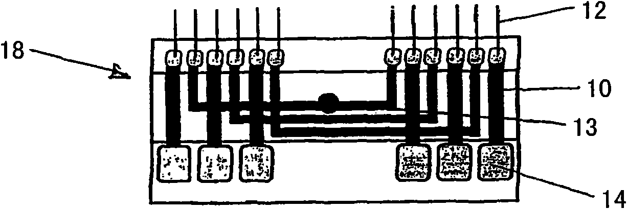

Image

  • Strain gauge rosette for internal stress measurement
  • Strain gauge rosette for internal stress measurement
  • Strain gauge rosette for internal stress measurement

Examples


Embodiment Construction

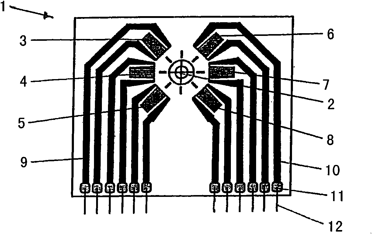
[0016] in the attached figure 1 shows a strain gauge rosette 1 as a borehole rosette on which three measuring grids 3, 4, 5 of the same type are arranged at an angular distance of 45° around the center of the borehole 2 at the same radial distance, with respect to the borehole A measuring grid 6, 7, 8 of the same type is arranged symmetrically on the opposite side of the measuring grid in the center of the hole 2.

[0017] The strain gauge flower 1 here comprises a plastic carrier layer 9 on which six conventional meander-shaped measuring grids 3 , 4 , 5 , 6 , 7 , 8 are arranged. In this case, all measuring grids 3 , 4 , 5 , 6 , 7 , 8 are arranged concentrically around a central drilling mark 2 . Here, the three left measuring grids 3 , 4 , 5 or the right measuring grids 6 , 7 , 8 are arranged around the drilling marks 2 as usual with three grid drilling patterns, wherein all measuring grids 3 , 4, 5, 6, 7, 8 have the same radial distance from the drilling mark 2. In this c...


PUM


Abstract

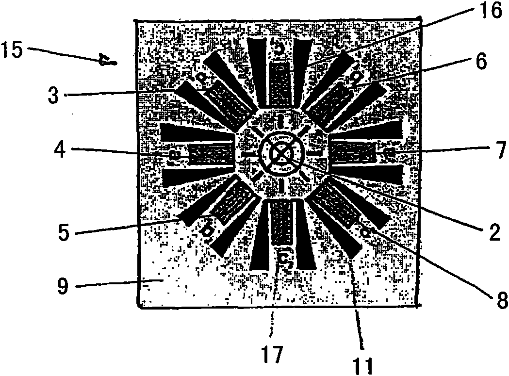
The invention relates to a strain gauge rosette for internal stress measurement on workpieces according to the bore hole method, comprising within an angular region of 0 - < 180 DEG at least three measurement grids 3, 4, 5 at equal distances and in different directions radially about a centering mark 2. The invention is characterized in that each of the at least three measurement grids 3, 4, 5 is associated with an equivalent measurement grid 6, 7, 8 that is disposed opposite and aligned in the same direction. To this end, all measurement grids 3, 4, 5, 6, 7, 8, 16, 17 have the same radial distance to the central marking 2. The opposing measurement grid pairs 3, 8,4, 7,5, 6,16, 17 of a tensile direction are connected or coupled to each other such that the measuring signals thereof are averaged.

Description

technical field [0001] The invention relates to a strain gage for measuring internal stresses on workpieces according to the drilling method according to the preambles of claims 1 and 10 . Background technique [0002] For a certain workpiece or component, it is usually necessary to determine whether there are internal stresses and their magnitude and direction. In this case, internal stresses are understood to be internal stresses in the component which act without external mechanical loading and which are under a spatially homogeneous and temporally constant temperature field. [0003] In order to measure such internal stresses, various test methods are given, by means of which the internal stress conditions on the surface and in the interior of the material can be ascertained. Drilling methods are usually used in areas close to the surface down to a depth of a few millimeters. In this case, a hole is drilled at a defined location of the component at which the internal s...

Claims


Application Information

Patent Timeline
Patent Type & Authority Applications(China)
IPC IPC(8): G01L5/00G01L1/22
CPCG01L5/0047G01L1/22
Inventor S·克莱因T·克莱克尔斯
Owner HOTTINGER BALDWIN MESSTECHNIK GMBH
Learn More