Pulse recoil deashing device special for air purifying equipment and deashing method

A technology of air purification equipment and ash removal device, which is applied in the direction of chemical instruments and methods, separation methods, and separation of dispersed particles, which can solve the problems of inability to complete filter cartridge ash removal, and achieve the effect of novel structural design and low noise

Inactive Publication Date: 2011-02-09
NANFANG ENVIRONMENT PURIFYING EQUIP HANGZHOU
View PDF5 Cites 4 Cited by
  • Summary
  • Abstract
  • Description
  • Claims
  • Application Information

AI Technical Summary

Problems solved by technology

However, the cleaning of the inner wall of the filter cartridge cannot be completed

Method used


Image

  • Pulse recoil deashing device special for air purifying equipment and deashing method
  • Pulse recoil deashing device special for air purifying equipment and deashing method
  • Pulse recoil deashing device special for air purifying equipment and deashing method

Examples


Embodiment 1

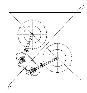
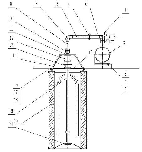
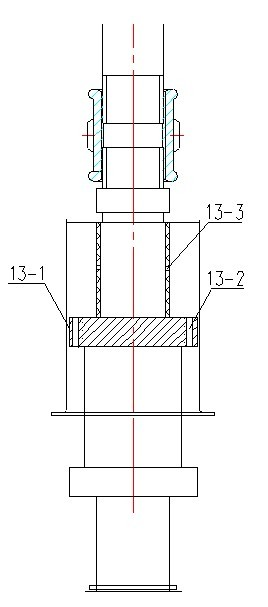
[0012] Embodiment 1: with reference to attached Figure 1-3 . Pulse recoil cleaning device for air purification equipment, which includes air purification and dust removal equipment. The dust removal equipment is equipped with a blowing dust removal system. The sheet 15 is fixed around the hole of the orifice plate, the off-line dust removal cover 15 covers the hole of the orifice plate and is located in the tripod 14, the upper end of the air sleeve 12 is connected with the upper end plate of the tripod 14, and the piston 13 is located in the air sleeve 12 Inside and under the action of gas under pressure, it moves up and down along the inner wall of the air sleeve. The upper end of the piston rod passes through the air sleeve 12 and is in a limited sliding fit with the limit nut 11. The limit nut 11 passes through the air guide tubes 6 and 8, the elbow 9. The clamp quick connection 7 and the pulse solenoid valve 1 are connected with the air bag 2. The air bag 2 is fixed (lo...

Embodiment 2

[0016] Embodiment 2: On the basis of embodiment 1, the self-cleaning method of the special pulse recoil dust removal device for air purification equipment, it includes air purification dust removal equipment, when it includes the filter cartridge 20 inner wall in the air purification dust removal equipment needs regeneration At this time, the air source with pressure supplies air to the air bag 2, and the pulse solenoid valve 1 is opened. After the pulsed air flow with pressure enters the piston 13 through the air guide pipes 6 and 8, it enters the blowing rotary frame 19 through the piston all the way, and passes through the piston plug ring all the way. The air hole 13-3 on the upper piston rod enters the air cavity formed by the upper part of the piston plug ring 13-1 and the air sleeve 12 and forces the piston 13 to move up and down according to the pulse air flow, and the piston 13 drives the offline dust cleaning cover 15 to move up and down Simultaneously, the blowing ro...


PUM


Abstract

The invention relates to a pulse recoil deashing device special for air purifying equipment, which has both blowing and self-deashing function and air cleaning and purifying function, and a deashing method. The device comprises air purifying and dust removing equipment, wherein a blowing and deashing system is arranged in the dust removing equipment; a triangle positioning frame in the blowing and deashing system is fixed around the pore of pore plate; an off-line deashing cover covers the pore of pore plate and is positioned in the triangle positioning frame; the upper end of an air jacket is connected with the upper end plate of triangle positioning frame; a piston is positioned in the air jacket and can move up and down along the inner wall of air jacket under the action of pressurized air; the upper end of piston rod passes through the air jacket and is in slide fit with a limit nut in a limited way; the limit nut is communicated with an air packet through a gas-guide tube and a pulse solenoid valve; the air packet is positioned on the pore plate; the lower end of piston rod is communicated with a blowing rotary frame; and the blowing rotary frame is positioned in a filter drum, and the lower end of the blowing rotary frame is tightly pressed against a hand wheel and is in running fit with the hand wheel. The device has the advantages of realizing an air regeneration filter drum, along with low noise, novel structural design, simplicity, reliability and practicability.

Description

technical field [0001] The invention relates to a special pulse recoil dust removal device and a dust removal method for air purification equipment, which not only have the function of spraying self-cleaning dust, but also have the function of air dust removal and purification, and belong to the field of air purification and dust removal equipment manufacturing. Background technique [0002] The patent number of the applicant is 200310116278.7, the name is "special vibrating dust removal mechanism for filter cartridge type dust removal and purification equipment", a special vibrating dust removal mechanism for filter cartridge type dust removal and purification equipment, which consists of positioning feet, connecting rods, eccentric mechanisms, vibrating The eccentric mechanism is driven by the motor. One end of the connecting rod is pinned to the transmission plate in the eccentric mechanism, and the other end is pinned to the positioning foot. The straight plate in the vib...

Claims


Application Information

Patent Timeline
Patent Type & Authority Applications(China)
IPC IPC(8): B01D46/42B01D46/24
Inventor 梅忠祥
Owner NANFANG ENVIRONMENT PURIFYING EQUIP HANGZHOU
Why Eureka
Try Eureka