Ultrasonic and infrared combined positioning device and positioning method thereof

A positioning device and positioning method technology, applied in the field of combining ultrasonic positioning and infrared, can solve the problems of inaccurate positioning, jumping to point b, etc., and achieve the effects of accurate positioning, reduced quantity, and reduced cost

Inactive Publication Date: 2011-02-09
GUANGDONG VTRON TECH CO LTD
View PDF2 Cites 12 Cited by
  • Summary
  • Abstract
  • Description
  • Claims
  • Application Information

AI Technical Summary

Problems solved by technology

However, the above-mentioned device has the following disadvantages: when the user writes on the infrared touch screen, the actual touch point of the pen tip is point c, but due to the habit of writing, the user's hand or sleeve will more or less block the point c in the figure. At point a, the mouse on the touch screen may jump to point b at this time, resulting in inaccurate positioning

Method used


Image

  • Ultrasonic and infrared combined positioning device and positioning method thereof
  • Ultrasonic and infrared combined positioning device and positioning method thereof
  • Ultrasonic and infrared combined positioning device and positioning method thereof

Examples


Embodiment 1

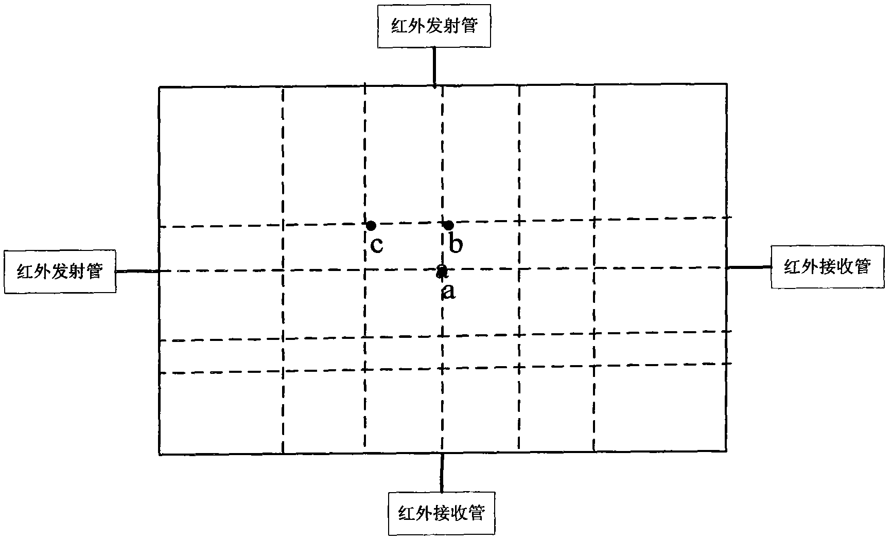
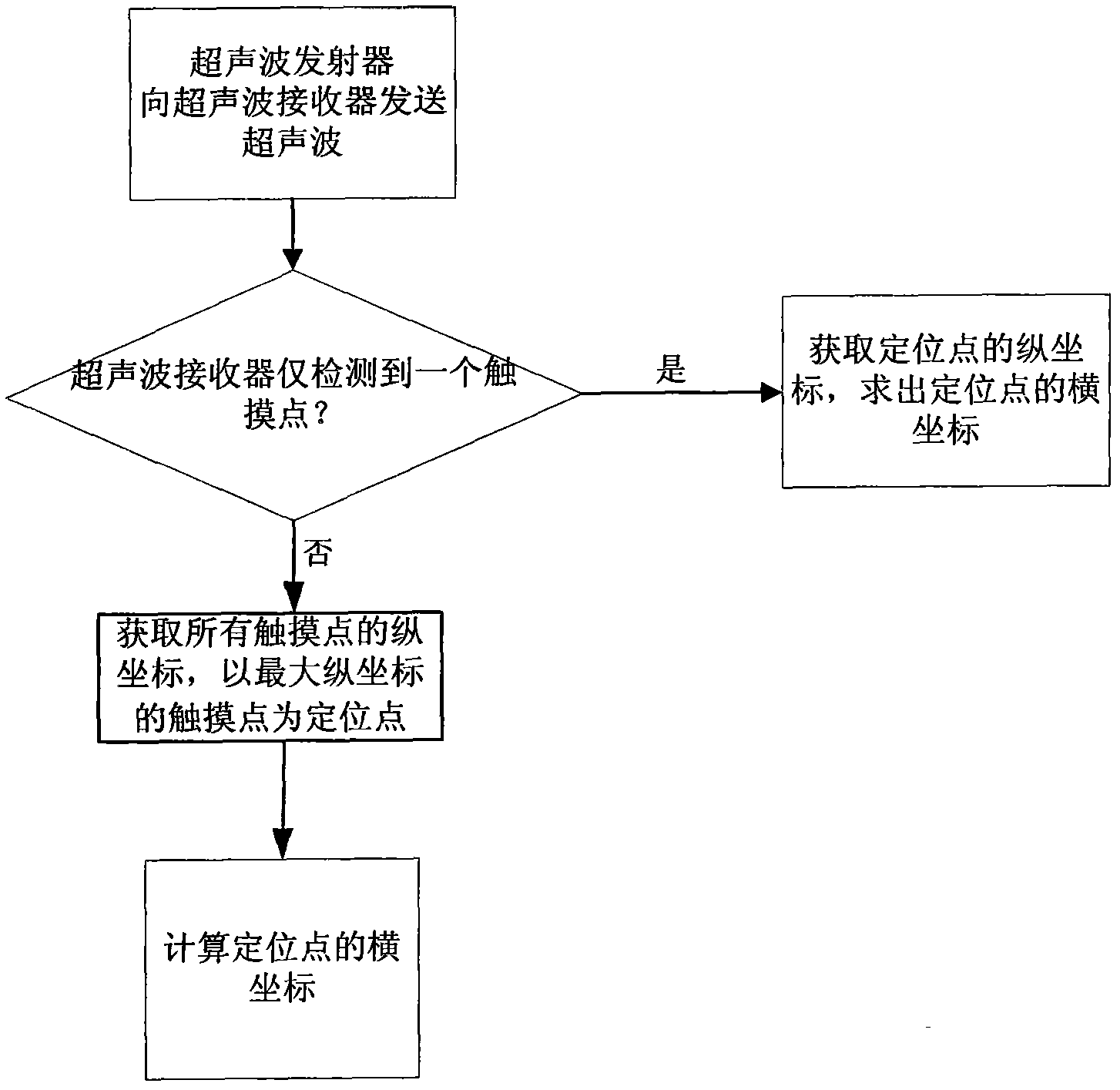
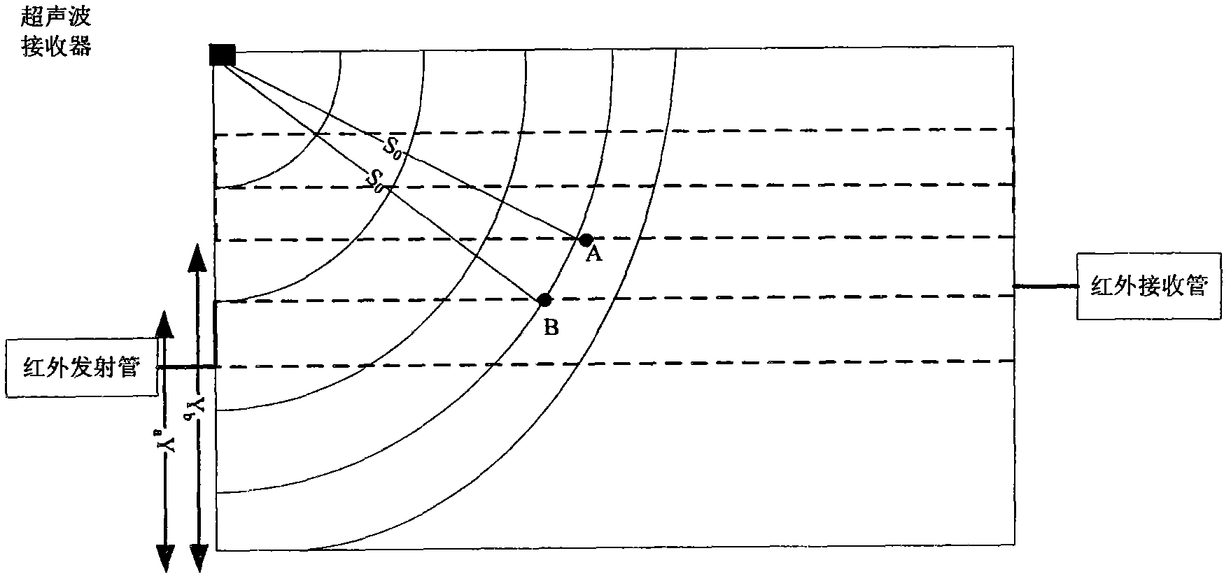
[0030] A positioning device combining ultrasonic and infrared, such as image 3 As shown, it includes a touch screen and a touch pen, wherein a microprocessor, an infrared emitting tube and an infrared receiving tube are installed on the touch screen, and the positioning device also includes an ultrasonic receiver and an ultrasonic transmitter, and the ultrasonic receiver is installed on the On the touch screen, the ultrasonic emitter is installed on the touch pen; the microprocessor is respectively connected with the infrared emitting tube, the infrared receiving tube and the ultrasonic receiver for signals.

[0031] The touch screen is rectangular, an infrared emitting tube is installed on the left frame of the touch screen, and an infrared receiving tube is installed on the right frame of the touch screen. The infrared rays emitted by the infrared emitting tube are parallel to the X-axis coordinates, and the infrared rays received by the infrared receiving tube are parallel...

Embodiment 2

[0044] A positioning device combining ultrasonic and infrared, such as Figure 4 As shown, it includes a touch screen and a touch pen, wherein a microprocessor, an infrared emitting tube and an infrared receiving tube are installed on the touch screen, and the positioning device also includes an ultrasonic receiver and an ultrasonic transmitter, and the ultrasonic receiver is installed on the On the touch screen, the ultrasonic emitter is installed on the touch pen; the microprocessor is respectively connected with the infrared emitting tube, the infrared receiving tube and the ultrasonic receiver for signals.

[0045] The touch screen is rectangular, an infrared emitting tube is installed on the left frame of the touch screen, and an infrared receiving tube is installed on the right frame of the touch screen. The infrared rays emitted by the infrared emitting tube are parallel to the X-axis coordinates, and the infrared rays received by the infrared receiving tube are paralle...

Embodiment 3

[0056] A positioning device combining ultrasonic and infrared, such as Figure 5 As shown, it includes a touch screen and a touch pen, wherein a microprocessor, an infrared emitting tube and an infrared receiving tube are installed on the touch screen, and the positioning device also includes an ultrasonic receiver and an ultrasonic transmitter, and the ultrasonic receiver is installed on the On the touch screen, the ultrasonic emitter is installed on the touch pen; the microprocessor is respectively connected with the infrared emitting tube, the infrared receiving tube and the ultrasonic receiver for signals.

[0057] The touch screen is an equilateral pentagon, such as Figure 5 As shown, an infrared emitting tube is installed on the left frame of the touch screen, and an infrared receiving tube is installed on the right frame of the touch screen. The infrared rays emitted by the infrared emitting tube are parallel to the X-axis coordinates, and the infrared rays received b...


PUM


Abstract

The invention discloses an ultrasonic and infrared combined positioning device, which comprises a touch screen and a touch pen, wherein a microprocessor, an infrared transmitting tube and an infrared receiving tube are arranged on the touch screen; and the positioning device also comprises an ultrasonic receiver and an ultrasonic transmitter, wherein the ultrasonic receiver is arranged on the touch screen, and the ultrasonic transmitter are arranged on the touch pen. The invention also discloses an ultrasonic and infrared combined positioning method, which comprises the following steps of: S1, determining the distance between a touch point and the ultrasonic receiver and judging whether the number of the touch point is only one by the ultrasonic receiver, and if so, entering the S2; otherwise, jumping to the S3; S2, detecting the Y-axis coordinate of a positioning point, and jumping to the S4; S3, detecting the Y-axis coordinates Y1,..., Yn of the touch points, and determining a positioning point; and S4, solving the X-axis coordinate of the positioning point, and returning to the S1. The positioning device has the advantages of accurate positioning, simple structure, low cost andthe like.

Description

technical field [0001] The present invention relates to the technical field of combination of ultrasonic positioning and infrared, in particular to a positioning device and a positioning method combining ultrasonic and infrared, which are especially applied to electronic display devices or other writing planes to realize writing board functions and intelligent input. Background technique [0002] Infrared touch screen devices currently on the market, such as figure 1 As shown, infrared emitting tubes or infrared receiving tubes are respectively arranged on the periphery of the infrared touch screen device. In the case of no touch, the infrared rays emitted by the infrared emitting tubes pass through the display area to reach the infrared receiving tubes, and are received by the infrared receiving tubes. Convert it into a usable electrical signal; in the case of touch, calculate the position of the touch point by detecting that the infrared grid in the display area is blocked...

Claims


Application Information

Patent Timeline
Patent Type & Authority Applications(China)
IPC IPC(8): G06F3/033G06F3/043G06F3/042G06F3/0354
Inventor 白宝国曾昭兴
Owner GUANGDONG VTRON TECH CO LTD
Why Eureka
Try Eureka