
Cooler

A cooling device and cooling unit technology, applied in cooling/ventilation/heating renovation, instruments, electrical digital data processing, etc., can solve the problems of excessive cost, redundancy and complexity, and achieve the effect of simplifying the overall structure

Inactive Publication Date: 2011-02-09
QISDA SUZHOU +1
View PDF3 Cites 2 Cited by
  • Summary
  • Abstract
  • Description
  • Claims
  • Application Information

AI Technical Summary

Problems solved by technology

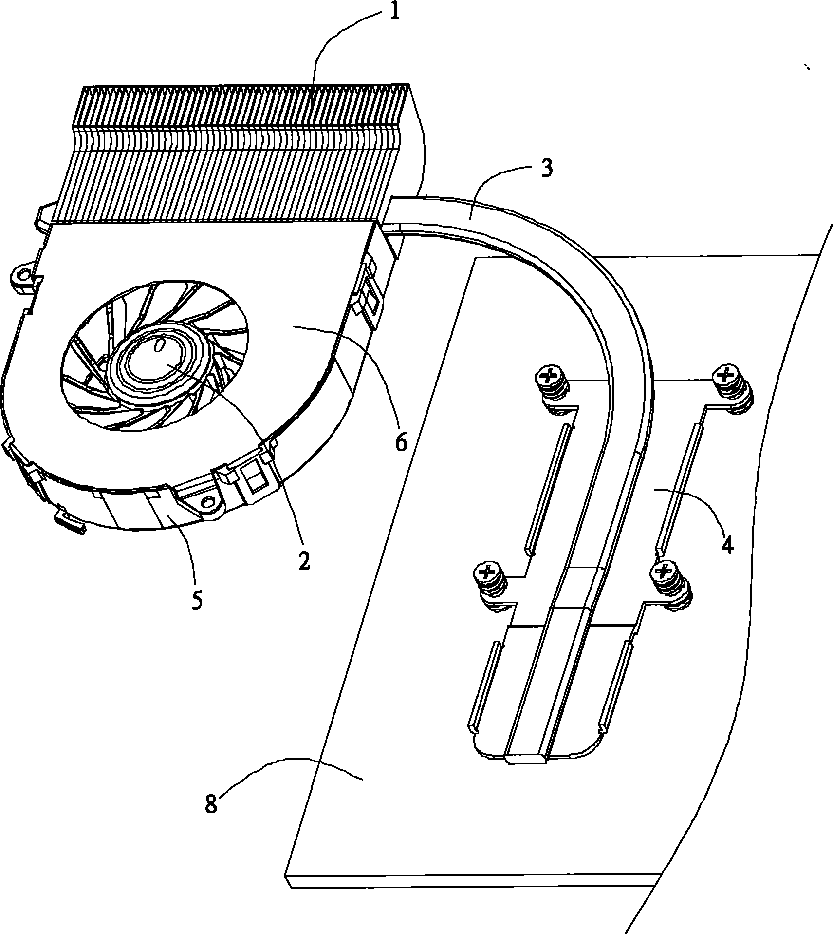
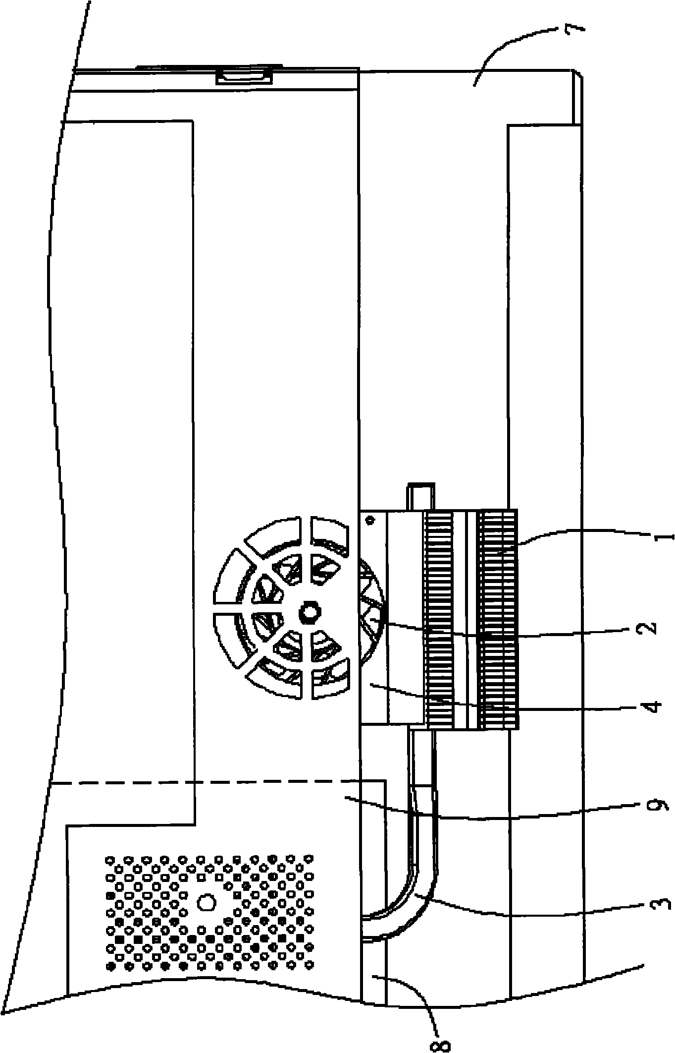
However, the above-mentioned structure is redundant and complicated in terms of achieving the purpose of protecting the fan, etc., which increases unnecessary costs

Method used


Image

  • Cooler
  • Cooler
  • Cooler

Examples


Embodiment Construction

[0023] The invention provides a cooling device. In a preferred embodiment, the cooling device of the present invention is used in an "all in one PC (AIO PC)" in which a screen and a computer are integrated. However, in other embodiments, the cooling device of the present invention can be used in other types of electronic devices to achieve effects such as heat dissipation of the electronic devices.

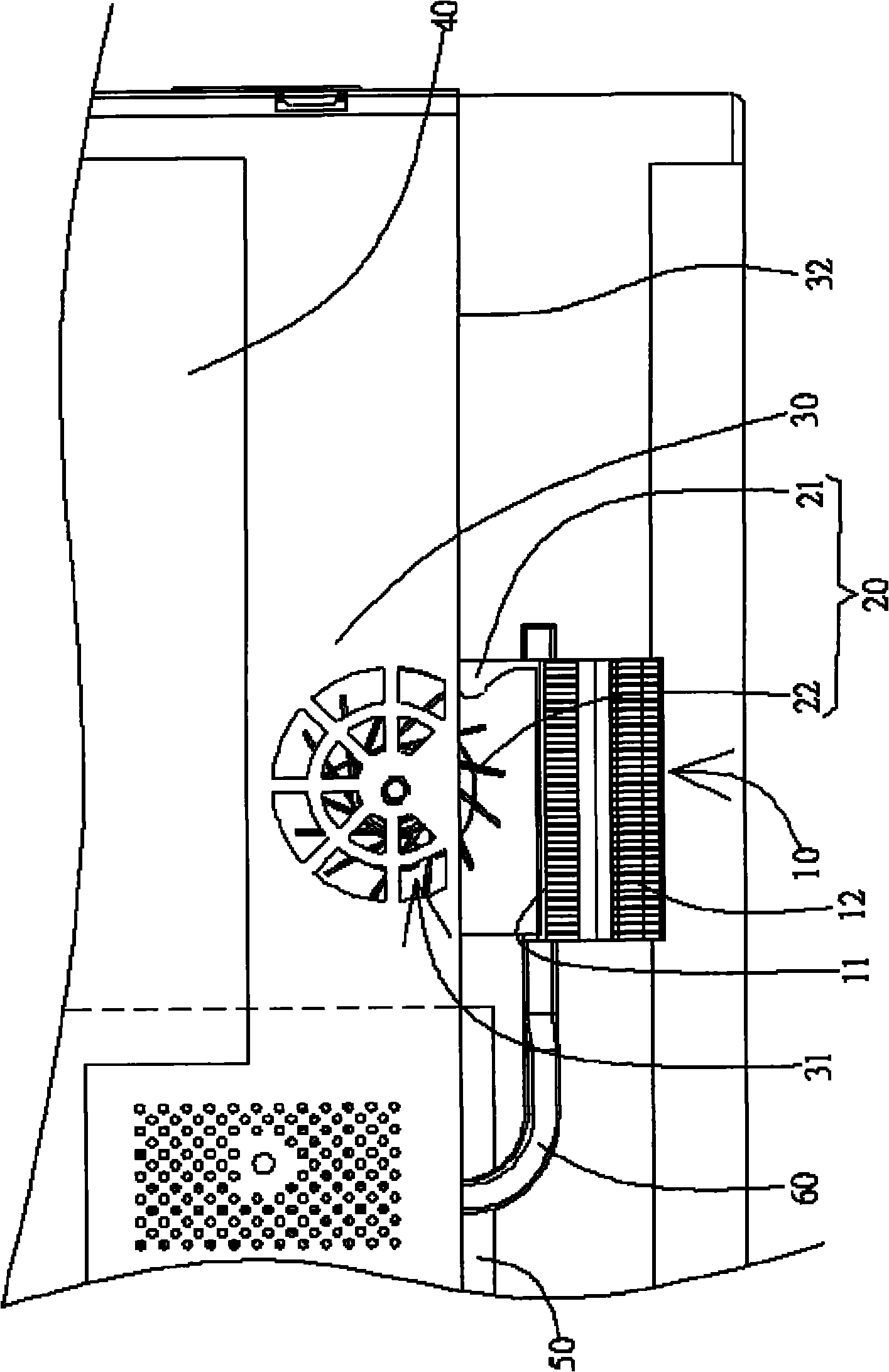
[0024] Figure 2A It is a schematic diagram of an embodiment of the cooling device of the present invention; Figure 2B for Figure 2A Schematic diagram of the fan unit of the cooling device shown. Such as Figure 2A and Figure 2B As shown, the cooling device includes a cooling unit 10 , a fan unit 20 , a metal shield 30 , a first electronic unit 40 , a second electronic unit 50 and a heat conduction unit 60 . The cooling unit 10 includes an air inlet 11 and an air outlet 12 at two opposite ends, wherein the air inlet 11 faces the fan unit 20 and the air outlet 12 faces upw...


PUM


Abstract

The invention provides a cooler which can be used for electronic devices. The cooler comprises a radiating unit, a fan unit, a metal sunshield and a first electronic unit, wherein the fan unit, which is arranged on one side of the radiating unit, comprises a shell and a fan; the fan encloses an open space for containing the fan; the metal sunshield shields part of the open space, so that the metal sunshield and the shell commonly surround the fan; one side of the open space is communicated with the radiating unit, so that the fan can blow air to the radiating unit; the metal sunshield shields the first electronic unit to prevent the first electronic unit from being subjected to electromagnetic interference, and a through hole is formed in the part which shields the open space; the first electronic unit is positioned on one side of the metal sunshield; and the radiating unit and the fan unit are positioned on the other side of the metal sunshield.

Description

【Technical field】 [0001] The present invention relates to a cooling device; specifically, the present invention relates to a cooling device used in an electronic device, which cools the electronic device in a way of dissipating heat. 【Background technique】 [0002] Many electronic devices such as integrated circuits, transistors, etc. will experience temperature rise during operation, and the temperature rise will often affect the working curve of the electronic device, and even cause burnout or explosion of the electronic device in severe cases. Especially for electronic devices with high power or high operating frequency, the former such as power transistors and the latter such as central processing units (Central Processing Unit, CPU), often generate quite high temperatures under normal operating conditions. [0003] Today's electronic devices are designed to be light, thin, short, and small in appearance, especially portable electronic devices such as notebook computers,...

Claims


Application Information

Patent Timeline
Patent Type & Authority Applications(China)
IPC IPC(8): G06F1/20H05K9/00H05K7/20
Inventor 苏永俊
Owner QISDA SUZHOU
Learn More