Eureka AIR delivers breakthrough ideas for toughest innovation challenges, trusted by R&D personnel around the world.

Disconnectable mooring assembly

A mooring and uncoupling technology, which is applied in the direction of special-purpose ships, buoys, ships, etc., can solve the problems of troublesome connection inspection and maintenance, small space, increased load, etc., and achieve the effect of easy establishment and detachment

Active Publication Date: 2011-02-09
BLUEWATER ENERGY SERVECES BV
View PDF8 Cites 2 Cited by
  • Summary
  • Abstract
  • Description
  • Claims
  • Application Information

AI Technical Summary

Problems solved by technology

In the operative position of the mooring assembly (the swivel is connected to and supported by the mooring buoy), the presence of the swivel makes establishing or disconnecting the connection difficult, while inspection and maintenance of the connection is cumbersome
Furthermore, the space between the mooring buoys and the swivel is known to be small for inspection, maintenance and handling of manifold features such as control consoles and pigs (required between mooring buoys and swivels) pig sender and / or receiver between components)
[0007] A further disadvantage is that during operation the weight of the rotating part is supported by the mooring buoys, which increases the load on the bearings between the central part and the outer part of the mooring buoys and indirectly increases the Loads acting on the ship

Method used


Image

  • Disconnectable mooring assembly
  • Disconnectable mooring assembly
  • Disconnectable mooring assembly

Examples


Embodiment Construction

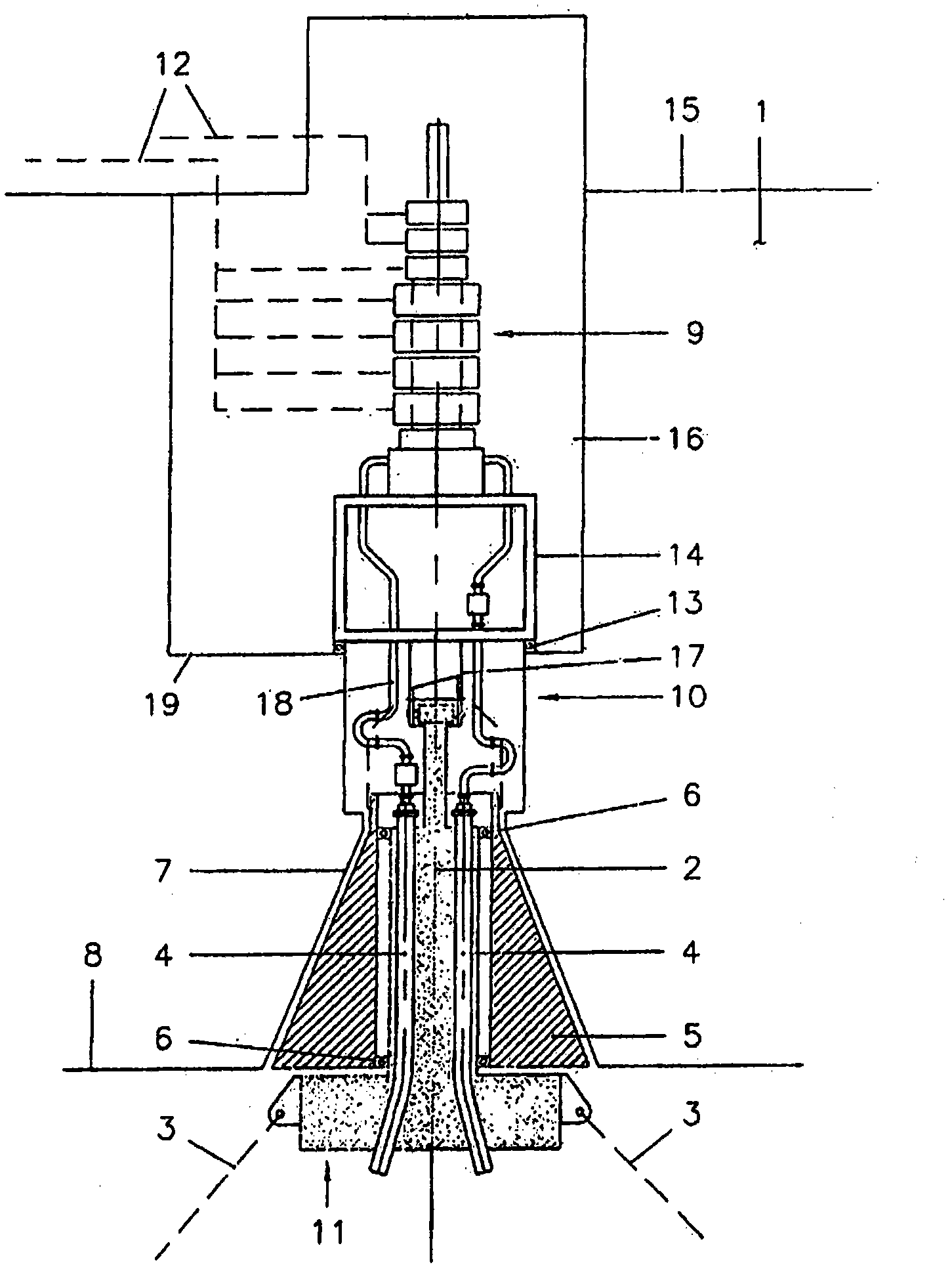
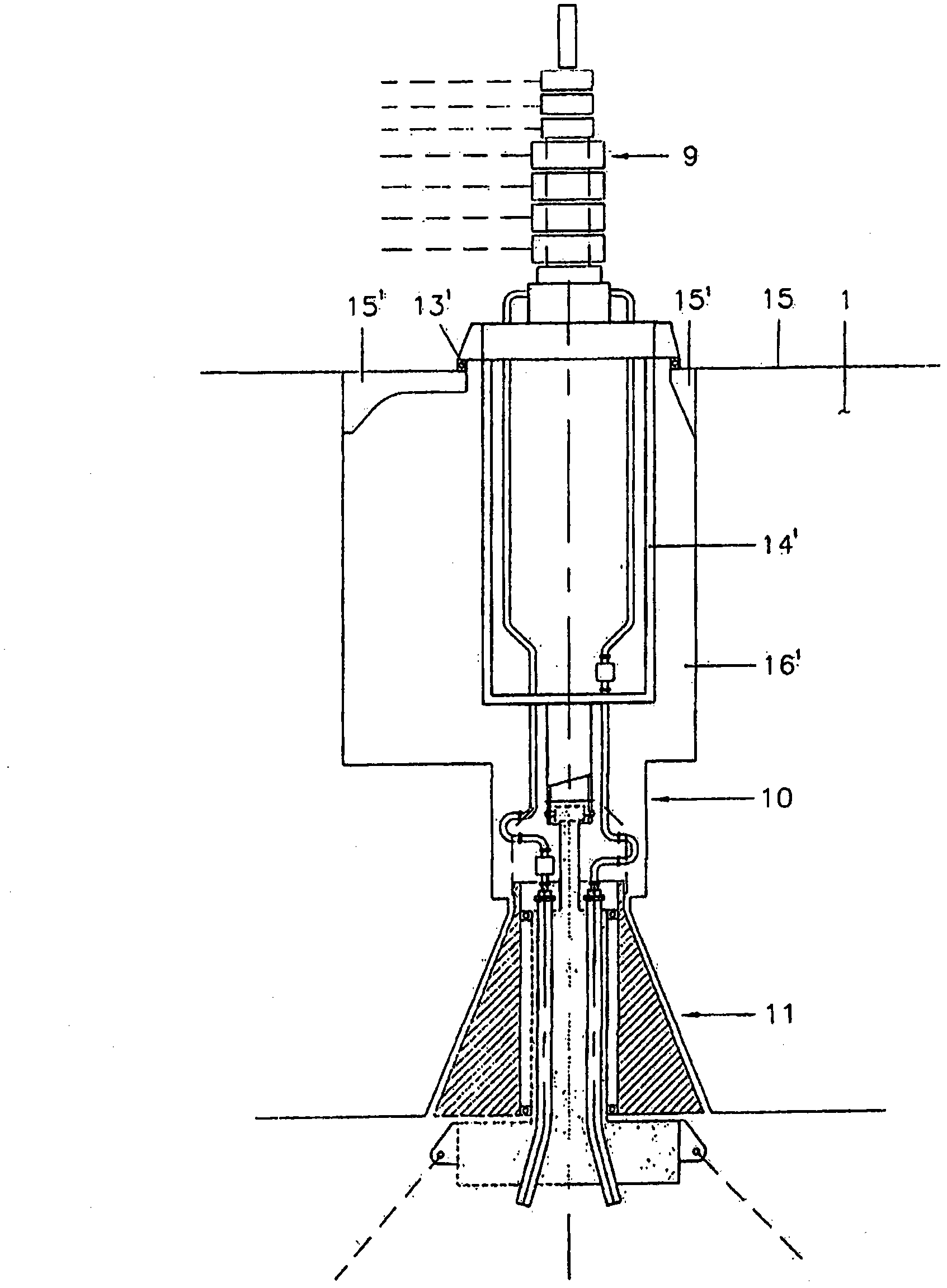
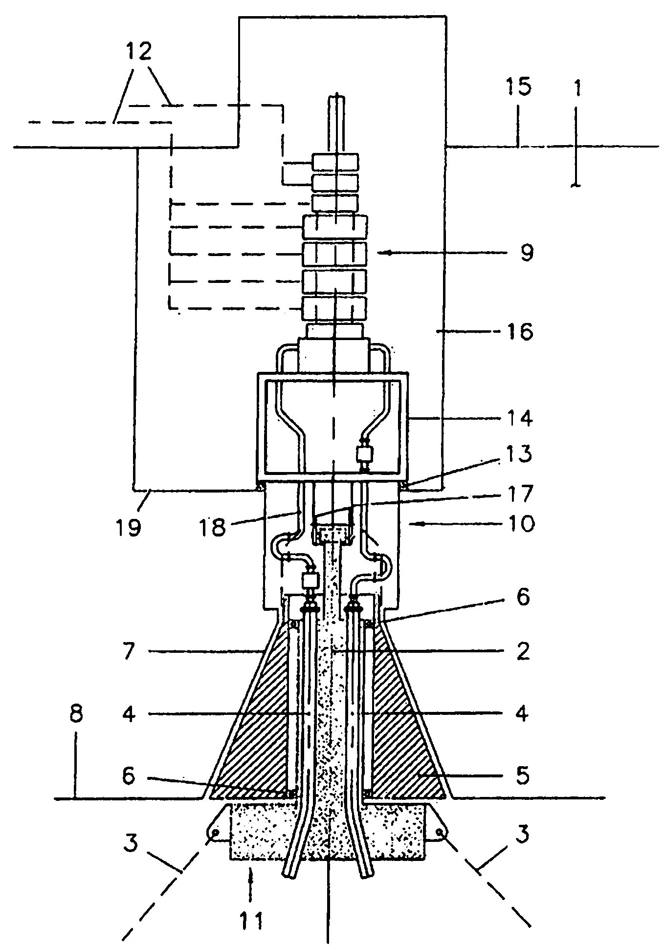
[0027] First reference figure 1 , figure 1 A detachable mooring assembly for a vessel 1 is shown. The detachable mooring assembly includes a mooring buoy 11, which is provided with a central component 2 for anchoring on the seabed through an anchor line 3, and the mooring buoy also includes a plurality of channels, each channel for Receiving riser 4. The riser can be connected to, for example, a subsea oil or gas well, and can be connected to the lower end of the mooring buoy, or can be (partially) pulled through the mooring buoy.

[0028] The mooring buoy 11 also includes an outer part 5 that surrounds the central part 2 and can rotate relative to the central part 2 (see, for example, the bearing assembly 6). The outer part 5 is adapted (by a suitable releasable locking device, which is not shown, but is known per se) to be accommodated and locked in the corresponding receiving opening 7 of the vessel 1 (usually but not exclusively, located in the vessel 1 In the keel 8 area)....


PUM


Abstract

A disconnectable mooring assembly for a vessel (1) comprises a mooring buoy (11) and a swivel positioned above the mooring buoy. The mooring buoy is provided with a central member (2) for being anchored to the seabed and comprises a number of passages each adapted for receiving a riser (4). The mooring buoy further comprises an outer member (5) surrounding the central member and capable of a rotation relative thereto. Said outer member is adapted to be housed in and locked to a corresponding receiving opening of the vessel. The swivel is located above the mooring buoy in such a manner that an interspace is defined between the mooring buoy and the swivel.

Description

Technical field [0001] The present invention relates to a detachable mooring assembly for ships, which includes a mooring buoy and a rotating part located above the mooring buoy, wherein the mooring buoy is provided with a central component that is used for anchoring at The mooring buoy includes a plurality of channels on the seabed, and each channel is used to receive a riser. The mooring buoy further includes an external component that surrounds the central component and can rotate relative to the central component. The external component is used for Loaded and locked in the corresponding receiving opening of the ship. Background technique [0002] Such a detachable mooring assembly enables the ship to swing with the wind around the mooring buoy, and is used to reduce the load caused by external factors (such as wind, water current, and waves). In severe conditions (for example, when a hurricane arrives), the mooring buoy can be disconnected from the ship and the ship can navi...

Claims


Application Information

Patent Timeline
IPC IPC(8): B63B22/02
CPCB63B22/026
Inventor B·C·H·霍赫费恩
Owner BLUEWATER ENERGY SERVECES BV
Why Eureka
Eureka Blog
Learn More