Optical signal processing

An optical signal and processor technology, which is applied in the field of optical signal processing and can solve the problems that fast dynamics and reconfigurability cannot meet performance.

Inactive Publication Date: 2011-02-09
TELEFON AB LM ERICSSON (PUBL)
View PDF5 Cites 3 Cited by
  • Summary
  • Abstract
  • Description
  • Claims
  • Application Information

AI Technical Summary

Problems solved by technology

[0003] Integrable solutions (such as those mentioned above) are attracting attention for their applicatio

Method used


Image

  • Optical signal processing
  • Optical signal processing
  • Optical signal processing

Examples


Embodiment Construction

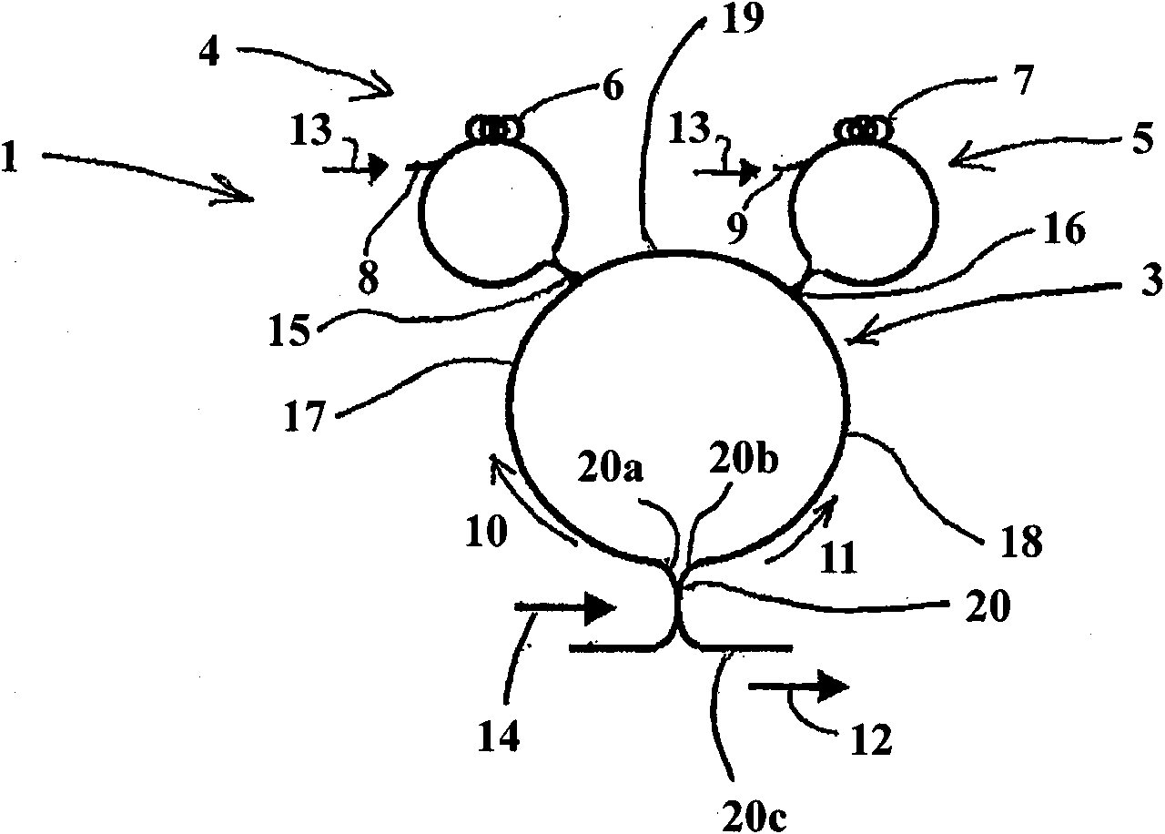
[0012] reference figure 1 , An optical signal processor 1 is shown, which includes an optical waveguide loop 3 and first and second nonlinear phase modulator loops 4 and 5 coupled to the optical waveguide loop 3. Each phase modulator loop includes highly nonlinear fiber (HNLF) sections 6 and 7 and corresponding input ports 8 and 9.

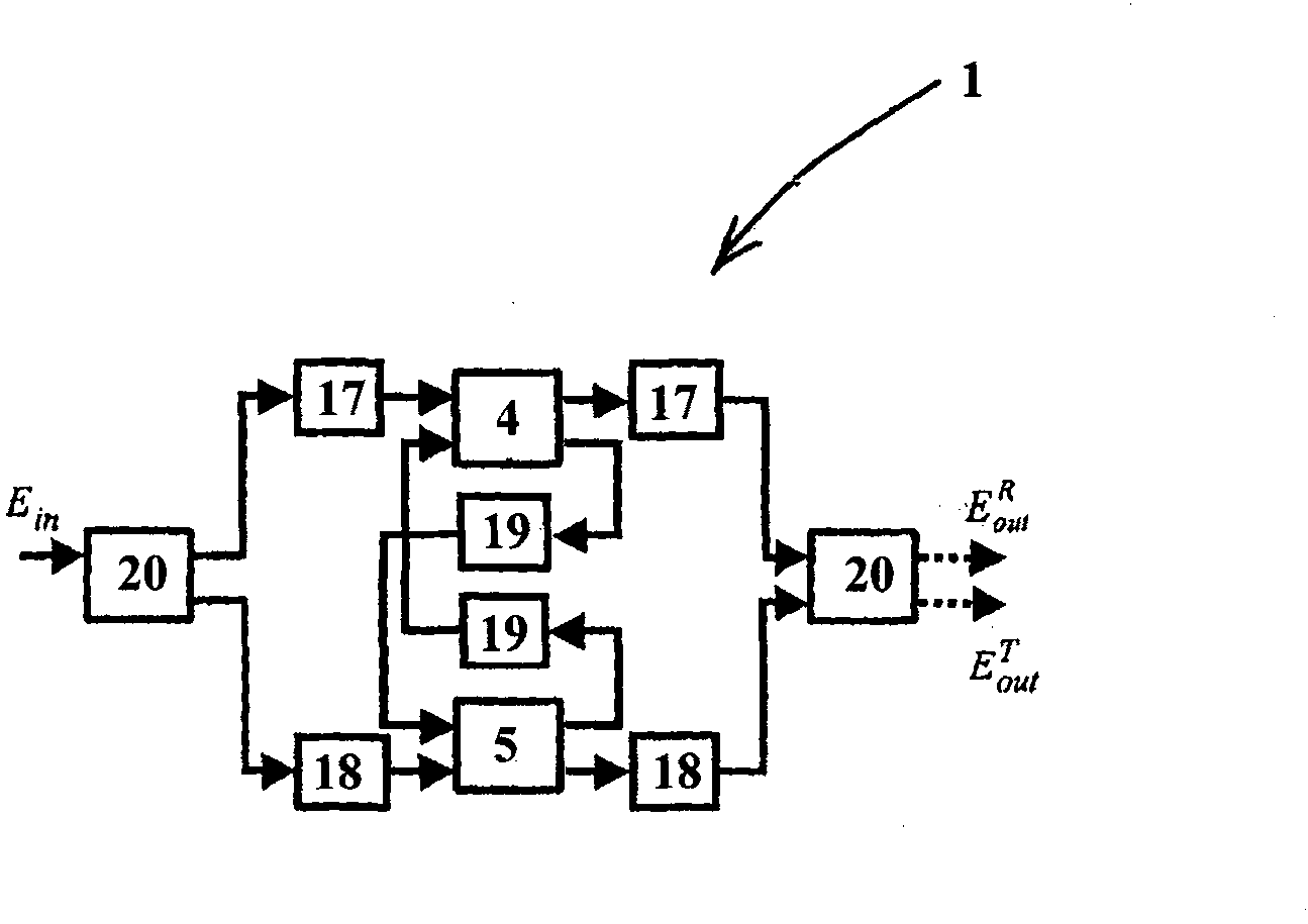
[0013] Each phase modulator loop 4 and 5 includes a polarization maintaining (PM) nonlinear optical loop mirror (NOLM) based on cross-phase modulation (XPM) (in figure 2 N on the right (k) To indicate that k=1, 2) are connected by three fiber spans 17, 18, and 19, and corresponding couplers 15 and 16 are provided for each phase modulator (as shown in C(2) ρ)). Generally, if D is the fiber span, then i=1, 2, 3, where Is the length of the i-th fiber. The optical splitter 20 feeds the input signal 14 to the processor 1. The optical splitter 20 has two input ports 20a and 20b to generate two input signals into the corresponding fiber spans 17 and 18,...


PUM


Abstract

Optical signal processor (1) comprising an optical waveguide loop (3), and first and second phase modulator loops (6, 7), each of the first and second phase modulator loops is in optical communication with the optical waveguide loop, and the first and second phase modulator loops each comprises a respective control signal input port (8, 9) to control phase modulation applied by the phase modulation loops, and the optical waveguide loop comprising two input ports (20a, 20b) to direct input signals (10, 11) in opposite senses in the optical waveguide loop and further comprising an output port (20c) to output resulting signals. The first and second phase modulator loops may comprise nonlinear optical loop mirrors. The processor may be an optical logic gate device.

Description

Technical field [0001] The present invention relates to optical signal processing. Background technique [0002] Due to electronic limitations such as computing and transmission speed, electromagnetic interference, power consumption, and insufficient bandwidth for ultra-fast applications, the need for all-optical signal processing technology is created. Known optical processors show the possibility of all-optical signal processing through various optical devices, such as semiconductor optical amplifiers (SOA), semiconductor saturable absorption mirrors (SESAM), and single or cascaded nonlinear optical loop mirrors (NOLM) Sex. [0003] Integrable solutions (such as those mentioned above) have attracted attention because of their applications, but currently they cannot meet acceptable performance in terms of fast dynamics and reconfigurability. Summary of the invention [0004] According to the present invention, there is provided an optical signal processor including an optical wav...

Claims


Application Information

Patent Timeline
IPC IPC(8): G02F1/35G02F3/00
CPCG02F3/00G02F1/3519
Inventor A·博戈尼L·波蒂E·拉泽里G·梅罗尼F·彭兹尼
Owner TELEFON AB LM ERICSSON (PUBL)
Why Eureka
Try Eureka