Left and right tooth lead screw type automatic centering clamp system

A technology that divides the fixture and the screw, which is used in clamping, manufacturing tools, workpiece clamping devices, etc.

Inactive Publication Date: 2011-02-16
SOUTH CHINA UNIV OF TECH
View PDF3 Cites 14 Cited by
  • Summary
  • Abstract
  • Description
  • Claims
  • Application Information

AI Technical Summary

Problems solved by technology

Although this method can make up for some deficiencies in existing equipment, it puts forward higher te

Method used


Image

  • Left and right tooth lead screw type automatic centering clamp system
  • Left and right tooth lead screw type automatic centering clamp system
  • Left and right tooth lead screw type automatic centering clamp system

Examples


Embodiment

[0026] like Figure 5 As shown, the left and right tooth screw type automatic centering fixture system of the present invention includes a base body 1 and a screw rod 6, the two ends of the screw rod 6 are respectively connected to the two ends of the base body 1 in rotation, and the two ends of the screw rod 6 The ends are respectively connected to the two ends of the seat body 1 in rotation, (of course, one end of the screw rod 6 can also be connected to one of the ends of the seat body 1 in rotation) The screw rod 6 is provided with a left clamping arm for clamping the workpiece. 7, right clamping arm 8, screw mandrel 6 and left clamping arm 7, right clamping arm 8 thread fit connection, screw mandrel 6 is divided into left section screw mandrel 7-1, right section screw mandrel 8-1, described left section wire The pitch of the screw thread of rod 7-1 and right section screw mandrel 8-1 is equal, and the direction of rotation is opposite. That is, the thread on the left sec...


PUM


Abstract

The invention discloses a left and right tooth lead screw type automatic centering clamp system, which comprises a seat body and a lead screw, wherein two ends of the lead screw are rotationally connected with two ends of the seat body; left and right clamping arms for clamping a workpiece are arranged on the lead screw; the lead screw is connected with the left and right clamping arms by screw threads; the lead screw is divided into a left lead screw and a right lead screw; the screw threads of the left lead screw and the right lead screw have equal thread pitch and opposite rotating directions; and when the lead screw is rotated in the nonuse rotating direction, two movable chucks generate synchronous relative movement or synchronous opposite movement. The system can be automatically adapted to automatic centering of the workpieces of different sizes, has wide application in automatic production lines, particularly has quite obvious application advantage under the condition that the requirement of the central line is higher than that of the outline, and does not need manual metering for correction and centering; and the system has a simple and reasonable structure, is convenient and quick to operate, and has good application and popularization values.

Description

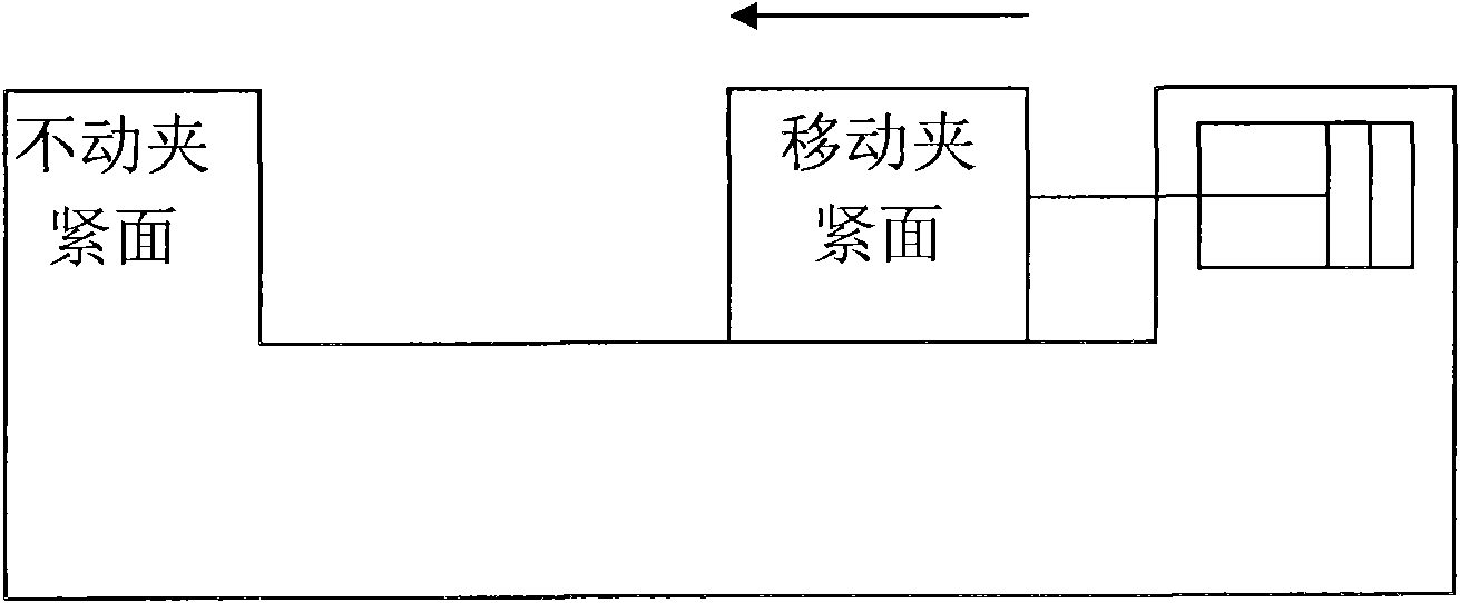
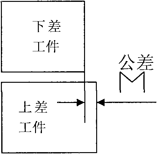
technical field [0001] The invention relates to a clamping device in the industrial field, in particular to a left and right screw rod type automatic centering clamp system. Background technique [0002] Clamping or vices of current industrial machines, automation equipment, etc. such as figure 1 or figure 2 As shown, its action principle is to fix one of the clamping surfaces, and then pass the screw ( figure 1 ), cylinder or cylinder ( figure 2 ) and so on to push the other clamping surface to move to the fixed clamping surface, so as to achieve the purpose of clamping the workpiece. However, in the actual production process, there is a tolerance M on the outer contour (or clamping surface) of the upper difference workpiece and the lower difference workpiece, such as image 3 As shown, in such a case, if the next process is to process on the centerline of the workpiece (such as drilling, milling, etc.), the outer contour tolerance M of the two workpieces will be brou...

Claims


Application Information

Patent Timeline
IPC IPC(8): B23Q3/06B25B11/00
Inventor 江伟
Owner SOUTH CHINA UNIV OF TECH
Why Eureka
Try Eureka