Lateral movably-connecting combined joint pipe of diaphram wall

An underground diaphragm wall and joint pipe technology, applied in sheet pile walls, underwater structures, water conservancy projects, etc., can solve the requirements of reducing the performance of extubation equipment, reducing the friction between the joint pipe and concrete and soil, etc. , to avoid the hidden danger of water leakage, to facilitate field operations, and to achieve good results.

Active Publication Date: 2011-11-16
TIANJIN SHENJI ENG +1
View PDF7 Cites 0 Cited by
  • Summary
  • Abstract
  • Description
  • Claims
  • Application Information

AI Technical Summary

Problems solved by technology

[0006] In order to solve the problems existing in the above-mentioned technologies, the purpose of the present invention is to provide an underground diaphragm wall living connection combined joint pipe, which is beneficial to reduce the friction between the joint pipe and concrete and soil, and reduce the performance requirements of the extubation equipment , to reduce the risk of deformation or damage to the soil under the guide wall, so that the extraction of the joint pipe can be carried out in a situation that is easy to control, easy to operate, and has a high safety factor

Method used


Image

  • Lateral movably-connecting combined joint pipe of diaphram wall
  • Lateral movably-connecting combined joint pipe of diaphram wall
  • Lateral movably-connecting combined joint pipe of diaphram wall

Examples


Embodiment Construction

[0024] Below in conjunction with accompanying drawing, the structure of underground diaphragm wall horizontal live connection combined joint pipe of the present invention is further described:
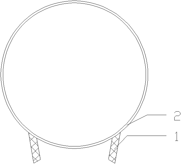
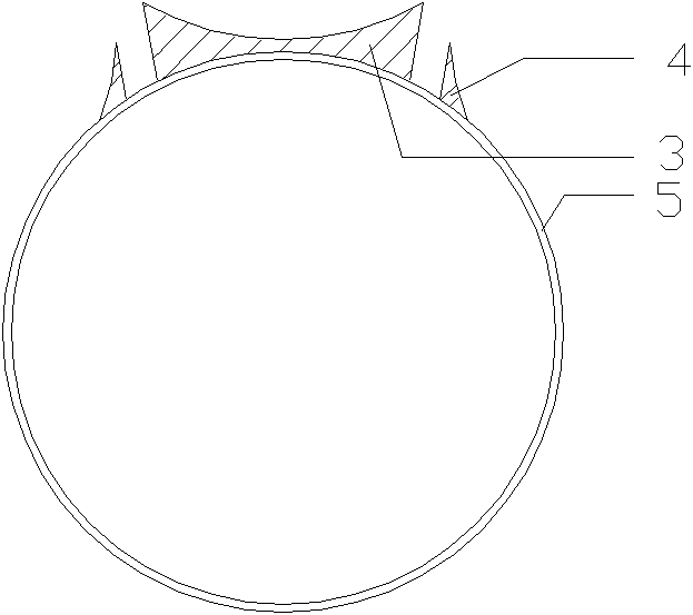
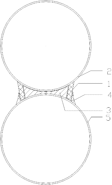
[0025] The design idea of ​​the combined joint pipe for horizontal movable connection of the underground diaphragm wall of the present invention is to allow two independent joint pipes to work together as a whole through buckle connection. Quantity, the live connection is characterized in that it can move separately during use, it is combined and connected together, and it is not restricted by the connection, forming an independent joint pipe for lifting operations. Thereby, the pull-out force of the joint pipe is reduced, and the risk of pulling out the joint pipe is reduced.

[0026] The combined joint pipe for transverse living connection of the underground diaphragm wall of the present invention has two independent first joint pipes 2 and second joint pipes 5, and the first joint p...


PUM


Abstract

The invention provides a lateral movably-connecting combined joint pipe of a diaphram wall. The movably-connecting combined joint pipe is mutually connected by buckles fixed on two independent joint pipes to form a combined joint pipe, and can be extracted by pulling the two independent joint pipes at the same position or malposition. The joint pipe has the advantages of being especially suitablefor solving the problem of the treatment on the joints of the joint pipe of the ultra-thick diaphram wall and sharing the two independent joint pipes so as to greatly bring convenience to the production, transportation and filed operations of the joint pipe. By adopting the occlusion connecting mode, the joint pipe can be extracted at malposition, thereby effectively reducing the risk that the joint pipe cannot be extracted due to overlarge extraction force, reducing the construction difficulty of extracting, ensuring the leakproofness of the diaphram wall joint and effectively avoiding the possibility of the circumferential motion of concrete and the potential hazards of water leakage of the joint seam.

Description

technical field [0001] The invention relates to an underground diaphragm wall joint treatment process in the fields of municipal administration, railways, ports, etc., in particular to an underground diaphragm wall transverse live connection combined joint pipe, which is suitable for the treatment of ultra-thick underground diaphragm wall joint pipe joints. Background technique [0002] The main steps in the construction of the underground diaphragm wall are: 1. First construct the guide wall of the underground diaphragm wall and leveling and compacting the site; 2. Use the special trenching equipment for the underground diaphragm wall to carry out the trenching operation, similar to the hole forming of cast-in-place piles; 3. Satisfy the After the design and construction specifications are required, place the circular joint pipe connecting the ground to the wall at the end of the groove section; 4. Lift and lower the processed steel cage; 5. Carry out underwater concrete pou...

Claims


Application Information

Patent Timeline
Patent Type & Authority Patents(China)
IPC IPC(8): E02D5/20E02D29/16E02D29/02
Inventor 郑建民申立民胡德喜魏方平赵明时
Owner TIANJIN SHENJI ENG
Why Eureka
Try Eureka