Supercharge Your Innovation With Domain-Expert AI Agents!

Novel heat exchanging device

A heat exchange device and a new type of technology can be used in household heating, heating methods, household heating and other directions. Reasonable design of air duct flow path and good heat exchange effect

Inactive Publication Date: 2011-02-16
GD MIDEA AIR-CONDITIONING EQUIP CO LTD
View PDF10 Cites 3 Cited by
  • Summary
  • Abstract
  • Description
  • Claims
  • Application Information

AI Technical Summary

Problems solved by technology

[0002] At present, when the micro-channel heat exchanger is used as the heat exchanger of the indoor unit of the cabinet air conditioner, condensed water will be generated on the surface. Installed between the headers, the headers are located on the upper and lower sides, and the straight section between the fins set between adjacent flat tubes and the air heat exchange is often horizontal, and water will appear on the edge; When the fins have slots, the condensed water will flow from the upper fins to the lower fins along the slots. Although the drainage is realized, due to the gap between the air inlet side fins and the air outlet side fins The combined structure is unreasonable. The condensed water of the upper fins needs to pass through all the lower fins to be finally discharged. The condensed water has a long flow distance, which affects the heat exchange effect during the flow process. The wind resistance is large, which hinders Air circulation reduces heat transfer efficiency

Method used


Image

  • Novel heat exchanging device
  • Novel heat exchanging device
  • Novel heat exchanging device

Examples


Embodiment Construction

[0032] The present invention will be described in further detail below through specific embodiments and in conjunction with the accompanying drawings.

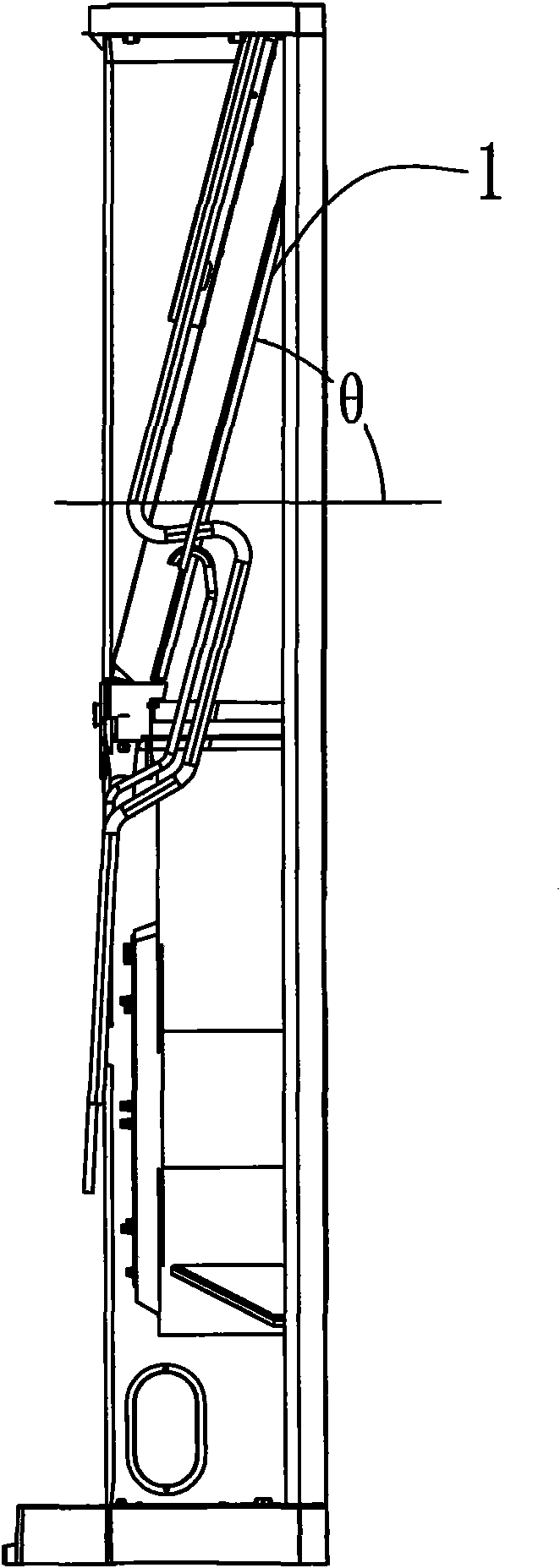
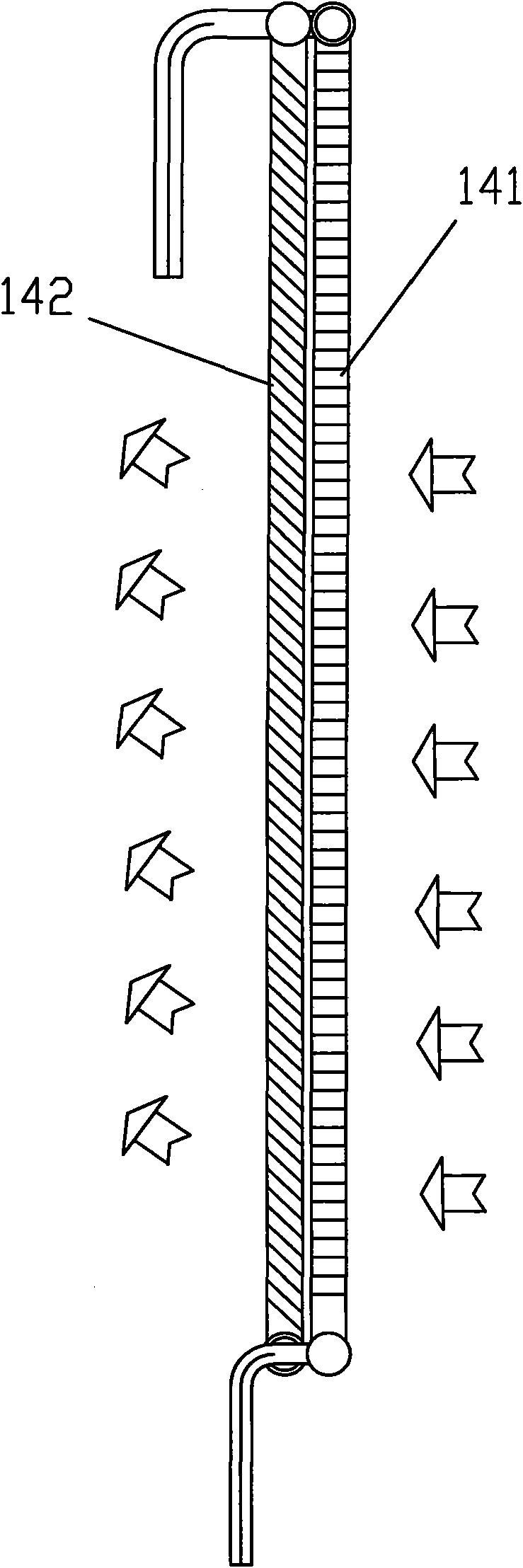
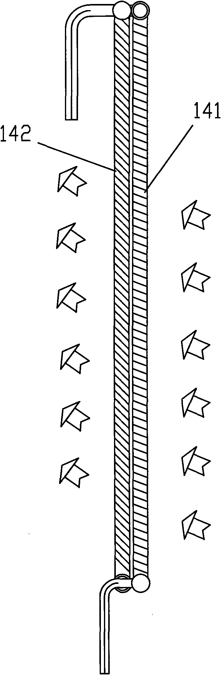
[0033] like figure 1 As shown, a new type of heat exchange device is applied to the heat exchanger of the indoor unit or outdoor unit of the cabinet air conditioner, such as an evaporator, which includes at least one microchannel heat exchanger 1 . See figure 1 , the microchannel heat exchanger arranged inside the indoor unit of the cabinet air conditioner forms an included angle θ with the horizontal direction, 30°≤θ≤90°. to combine Image 6 It can be seen that the microchannel heat exchanger 1 generally includes a first header 11, a second header 12 arranged in parallel with a certain distance from the first header 11, and a second header connected between the first header 11 and the second header. Among the flow tubes 12 are several flat tubes 13 spaced at a certain distance from each other and several fins 14 respective...


PUM


Abstract

The invention discloses a novel heat exchanging device which comprises at least one microchannel heat exchanger. The microchannel heat exchanger comprises a first collecting pipe, a second collecting pipe which is parallel to the first collecting pipe and has a certain distance with the first collecting pipe, a plurality of flat pipes arranged at intervals between the first collecting pipe and the second collecting pipe, and a plurality of fins respectively arranged between every two adjacent flat pipes, wherein each flat pipe is internally provided with a plurality of microchannels communicating the first collecting pipe and the second collecting pipe. The heat exchanging device also comprises a wind inlet side fin and a wind outlet side fin which are respectively arranged on at least two microchannel heat exchangers which are arranged side by side and spaced with a certain distance, or the wind inlet side fin and the wind outlet side fin are arranged on the same microchannel heat exchanger, the surface of the wind inlet side fin is vertical to the surface of the heat exchanger or inclines upwards and towards a wind outlet side, and the surface of the wind outlet side fin inclines upwards and towards the wind outlet side. The invention has the advantages of reasonable wind channels and flow paths, which is beneficial to the improvement of heat exchanging capacity of the heat exchangers, the reduction of the resistance of wind channels and the realization of extremely good heat exchanging effect.

Description

Technical field: [0001] The invention relates to a novel heat exchange device, which belongs to the technical field of air conditioning. Background technique: [0002] At present, when the micro-channel heat exchanger is used as the heat exchanger of the indoor unit of the cabinet air conditioner, condensed water will be generated on the surface. Installed between the headers, the headers are located on the upper and lower sides, and the straight section between the fins set between adjacent flat tubes and the air heat exchange is often horizontal, and water will appear on the edge; When the fins have slots, the condensed water will flow from the upper fins to the lower fins along the slots. Although the drainage is realized, due to the gap between the air inlet side fins and the air outlet side fins The combined structure is unreasonable. The condensed water of the upper fins needs to pass through all the lower fins to be finally discharged. The condensed water has a long ...

Claims


Application Information

Patent Timeline
Patent Type & Authority Applications(China)
IPC IPC(8): F24F13/22F25B39/02F25B39/00F24F13/30F28F1/12
Inventor 徐绍勇佐藤宪一郎林飞任志洁
Owner GD MIDEA AIR-CONDITIONING EQUIP CO LTD
Features
  • R&D
  • Intellectual Property
  • Life Sciences
  • Materials
  • Tech Scout
  • Unparalleled Data Quality
  • Higher Quality Content
  • 60% Fewer Hallucinations
Learn More