Ultrasonic wave/infrared combined locating device and locating method thereof
A positioning method, ultrasonic technology, which is applied in the field of combining ultrasonic positioning and infrared, can solve problems such as complex structures, and achieve the effects of wide application range, low cost, and accurate positioning
- Summary
- Abstract
- Description
- Claims
- Application Information
AI Technical Summary
Problems solved by technology
Method used
Image

Examples
Embodiment 1
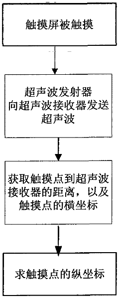
[0030] A positioning device combining ultrasonic and infrared, such as figure 2 As shown, it includes a touch screen and a touch pen, wherein a microprocessor, an infrared emitting tube, an infrared receiving tube and an ultrasonic receiver are installed on the touch screen, and an ultrasonic transmitter is installed on the touch pen; The infrared transmitting tube, the infrared receiving tube and the ultrasonic receiver are signal-connected.
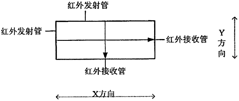
[0031] The touch screen is rectangular, the infrared emitting tube is installed on the upper frame of the touch screen, and the infrared receiving tube is installed on the lower frame of the touch screen.
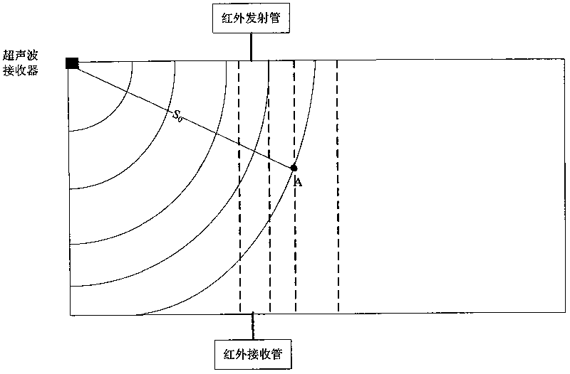
[0032] The infrared rays emitted by the infrared emitting tube are parallel to the Y axis, and the infrared rays received by the infrared receiving tube are parallel to the Y axis. The coordinate system is established with the bottom left corner of the touch screen as the coordinate origin.
[0033] There is a single ultrasonic re...
Embodiment 2
[0045] A positioning device combining ultrasonic and infrared, such as Figure 4 As shown, it includes a touch screen and a touch pen, wherein a microprocessor, an infrared emitting tube, an infrared receiving tube and an ultrasonic receiver are installed on the touch screen, and an ultrasonic transmitter is installed on the touch pen; The infrared transmitting tube, the infrared receiving tube and the ultrasonic receiver are signal-connected.
[0046] The touch screen is rectangular, the infrared receiving tube is installed on the upper frame and the right frame of the touch screen, and the infrared emitting tube is installed on the lower frame and the left frame of the touch screen.
[0047] The infrared rays emitted by the infrared emitting tube form an acute angle with the longitudinal Y axis or the transverse X axis, and the included angle is 45 degrees. The coordinate system is established with the bottom left corner of the touch screen as the coordinate origin.
[004...
Embodiment 3
[0058] A positioning device combining ultrasonic and infrared, such as Figure 5 As shown, it includes a touch screen and a touch pen, wherein a microprocessor, an infrared emitting tube, an infrared receiving tube and an ultrasonic receiver are installed on the touch screen, and an ultrasonic transmitter is installed on the touch pen; The infrared transmitting tube, the infrared receiving tube and the ultrasonic receiver are signal-connected.
[0059] The touch screen is rectangular, the infrared emitting tube is installed on the upper frame of the touch screen, and the infrared receiving tube is installed on the lower frame of the touch screen.
[0060] The infrared rays emitted by the infrared emitting tube are parallel to the Y axis, and the infrared rays received by the infrared receiving tube are parallel to the Y axis. The coordinate system is established with the bottom left corner of the touch screen as the coordinate origin.
[0061] There are two ultrasonic receiv...
PUM
 Abstract
Description
Claims
Application Information
 - R&D
- Intellectual Property
- Life Sciences
- Materials
- Tech Scout
- Unparalleled Data Quality
- Higher Quality Content
- 60% Fewer Hallucinations
Browse by: Latest US Patents, China's latest patents, Technical Efficacy Thesaurus, Application Domain, Technology Topic, Popular Technical Reports.
© 2025 PatSnap. All rights reserved.Legal|Privacy policy|Modern Slavery Act Transparency Statement|Sitemap|About US| Contact US: help@patsnap.com